Setting Up Production Testing for the PCM5122 Audio DAC
With testing complete for the PCM5122 Audio DACs and the passive part load out complete, then it is time to get the design ready for production. The board is fairly simple however it requires full functionality testing after being manufactured to ensure functionality. The board does not need programming but the PCM5122 needs to be configured before it can output audio.
Since the PCM5122 needs both I2C and I2S to function I decided the best plan for testing was a bed of nails style with pogo pins similar to the test fixture I designed a few years ago. So instead of having to plug in an input data cable and then an analog output cable, I will just need to place the PCB into the fixture to test, which greatly speeds up the testing procedure. To configure the PCM5122 and give it digital I2S audio, I choose to use the Arduino Zero development board because t supports I2S audio. It also has software libraries for the I2S which should speed up development of the fixture’s software.
Modifying the PCM5122 Audio DAC PCB for Pogo Pin Contacts
In order to make contact with the pogo pins on the test fixture, exposed contacts on the bottom side of the PCB are needed. I placed the contacts as close as I could to the input header and the audio output. I used 1mm diameter contacts. Also, make sure to not put paste on these contacts since you want them to be as clean as possible. No-clean paste will leave a residue coating that can prevent the pogo pin from making clean contact with the PCB.
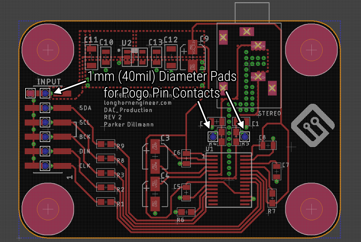
Layout DAC Pogo Pin 1
Board layout with the pogo pin contacts added to the bottom side of the PCB.
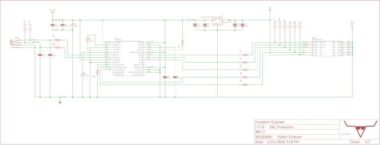
Schematic DAC Pogo Pin 768x294
Schematic for the DAC board. The pogo pin test points are the designators TP#.
Design of the Test Fixture
The Arduino Zero has most of the supporting hardware already designed and manufactured, therefore the fixture design is fairly simple. The fixture will need to be able to power the DAC board on and off and disconnect communication lines. A button that is used to tell the Arduino to begin the test is also needed. Then pogo pins will be needed to connect the fixture to the DAC board.
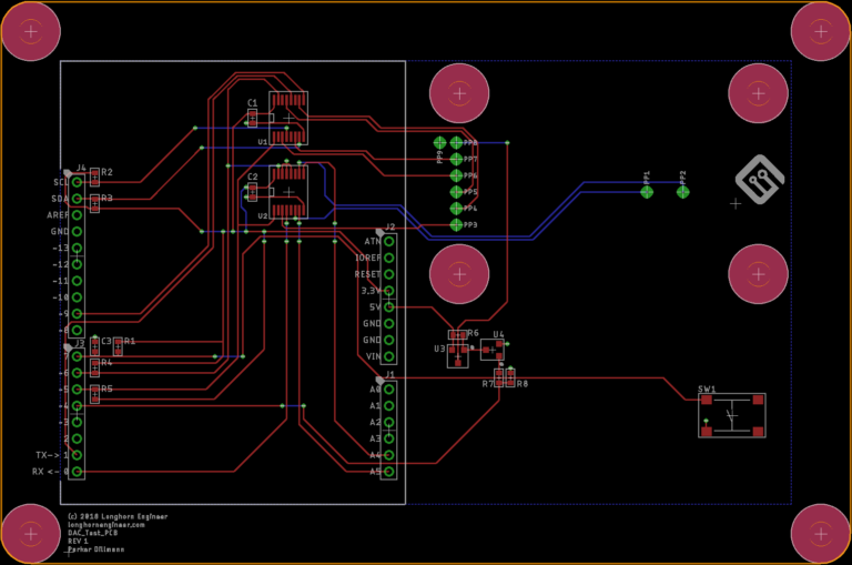
Layout DAC Fixture 768x509
Board layout for the test fixture. Arduino on the left and the DAC board goes on the right.
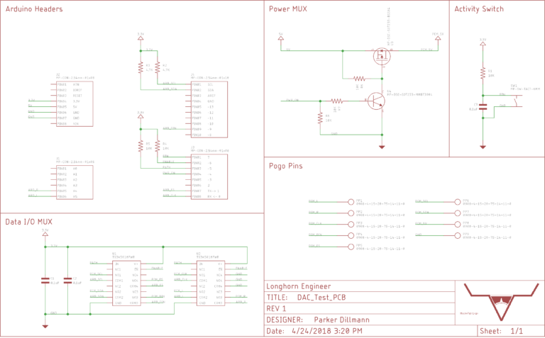
Schematic DAC Fixture 768x477
Schematic for the fixture.
The pogo pins I choose to use are part number Mill-Max 0908-4-15-20-75-14-11-0. Mill-Max’s through hole series of pogo pins have come to be some of my favorites since they have a decent stroke distance which reduces non contact issues. Also, they have a step on the through hole pin so they get soldered to the same depth which takes the guess work out of setting up the pogo pins.
Power switching for the DAC Board is done with a P-channel mosfet (part number BSS84) for high side switching and a MMBT3904 transistor to make sure the gate gets turned fully on and off.
For disconnecting the pogo pins I choose the TS3A5018PWR which is a SMT analog switch. The reason to switch these communication lines is even if the DAC board’s power rail is turned off with the P-channel mosfet, then there can still be leakage current through the data lines and up internal ESD protection or internal pullups on the PCM5122. This can cause weird states and could possibly damage the electronics. Being able to fully disconnect the data lines therefore prevents this issue.
With the PCB for the fixture finally designed, the last part was to design a mount to hold the DAC board over the pogo pins. It should self center the DAC board and hold it at the right distance away. I was able to utilize the mounting holes in the DAC board as centering pins. To calculate the thickness of the mount I looked at the pogo pins.
The 0908-4-15-20-75-14-11-0 pogo pins are 0.335″ tall and have a half stroke distance of 0.0275″. Subtracting these gives 0.3075″ which is what I set mount thickness to be. Therefore when the DAC board goes onto the mount, it will be compressing the pogo pins to half their stroke length. The pogo pin clearance holes are 40 mils in diameter, as a result clearing the pogo pins with plenty of tolerance. I designed the mount in SketchUp then exported it as a .STL file for 3D printing.
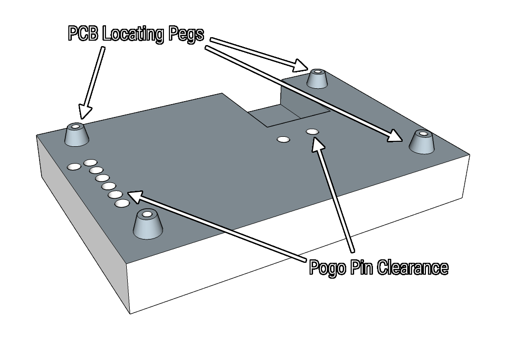
Dac Fixture PCB Mount 1
Mount for the fixture. First, this goes onto the fixture by sliding over the pogo pins. The DAC board then slides down the PCB locating pegs. Finally it presses into the pogo pins, completing the electrical connection.
Files For The Project
If you would like to take a look at the files for the PCM5122 DAC Board, Fixture PCB, and the Fixture Mount I uploaded them to the MacroFab Github Repo. Feel free to replicate or expand on the project. PCB board files are in Eagle and the Fixture Mount was designed in SketchUp.
MacroFab/Macro_Articles/PCM5122_DAC
Recap
In conclusion, with the DAC board modified for production testing and the fixture for testing design, this board is almost complete. The next article will be the final one in this series, so it will cover the code for the Arduino Zero on the fixture as well as final testing of the DAC board.
Read about the fixture code and final testing of the PCM5122 Audio DAC now.
Was this post helpful? Have other questions? Let us know in the comments below.
Related Topics
Improve Your Next PCB Prototype: Better Debugging, Testing, and Reliability
Enhance PCB prototypes with debugging, testing, and reliability features. Get design tips like test points, power management, and signal integrity testing
Reasons Your EMS Development Team Can't Deliver on Time
Sustaining operations demands an enormous effort that leaves you worn out. Unstable external pressures keep you wondering what tomorrow will bring.
Tolerances Stack Up
Electrical and mechanical components have production tolerances within the design with variance over their manufacturing life.
About MacroFab
MacroFab offers comprehensive manufacturing solutions, from your smallest prototyping orders to your largest production needs. Our factory network locations are strategically located across North America, ensuring that we have the flexibility to provide capacity when and where you need it most.
Experience the future of EMS manufacturing with our state-of-the-art technology platform and cutting-edge digital supply chain solutions. At MacroFab, we ensure that your electronics are produced faster, more efficiently, and with fewer logistic problems than ever before.
Take advantage of AI-enabled sourcing opportunities and employ expert teams who are connected through a user-friendly technology platform. Discover how streamlined electronics manufacturing can benefit your business by contacting us today.