Intro to Tag Connect / AVR MCU
Previously we introduced Tag-Connect pogo pin connectors for programming. This time we will be designing an AVR board based on the ATmega328P, which is used on the Arduino platform. The AVR board will have a TC2030-IDC connection for programming over ISP and an LED to show functionality. The heart of the board will be the tried-and-tested ATmega328P in the QFP-32 package (-AU). We will be using Eagle as our EDA tool for this example. Make sure to get the latest version of the MacroFab part libraries. The sample files for this board can be found in the Macro_Articles GitHub repository where you should locate the .brd and .sch files for the AVR_Tag-Connect board.
Pin-out for the Tag-Connect
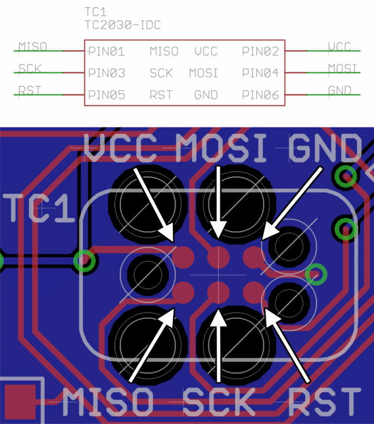
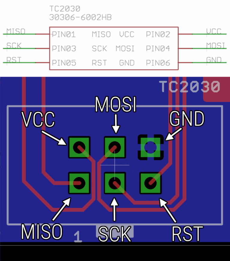
The pin-out for the TC2030-IDC connector for AVR ISP is below. Figure 1 shows the pin-out on the PCB board side. Figure 2 shows the pin-out for the 02×03 header for the programmer side.
AVR_Tag-Connect Example Board
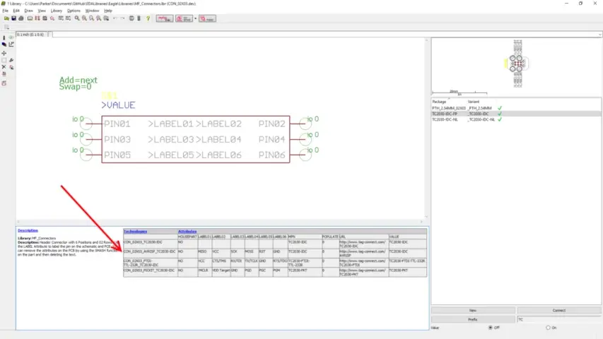
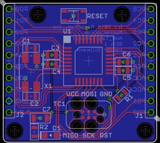
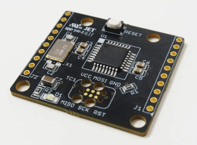
The AVR_Tag-Connect board is a bare bones example of the minimum needed to get an ATmega328P working and programmed. The part that will connect to the Tag-Connect cable is called “CON_02X03_AVRISP_TC2030-IDC” and can be found under the MF_Connectors library (Figure 3). The schematic for the AVR_Tag-Connect board is shown on Figure 4 and the board layout is shown on Figure 5.

Example Arduino Code
Now that the board is built, we can test it with some example code (Figure 6).
To test if the AVR_Tag-Connect example board is working we are going to use a modified version of the Blink program that is included in the Arduino IDE. The LED on the AVR_Tag-Connect board is connected to PB0 which corresponds to Digital Pin 8 in the Arduino world. The code can be found here or copied from below. The code should blink the LED D1 on the board.
void setup() {
    pinMode(8, OUTPUT);
}

void loop() {
    digitalWrite(8, HIGH);
    delay(1000);
    digitalWrite(8, LOW);
    delay(1000);
}
Programming the AVR_Tag-Connect Example Board
To connect the AVR_Tag-Connect example board to our AVR ISP programmer we are going to use the AVRISP2TC board. You can plug the TC2030-IDC-NL Tag-Connect cable directly into most AVR ISP programmers, but we want to provide power to the example board. To provide power to the AVRISP2TC board we need to connect the Tag-Connect cable to the AVR ISP programmer AND to an external source of power. In this case we will be using USB power, which reduces how many cables that are needed to connect to the AVR_Tag-Connect example board during programming, which also speeds up production programming. See Figure 7 for how to connect up the AVRISP2TC board to your AVR ISP programmer.
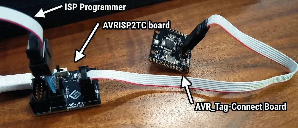
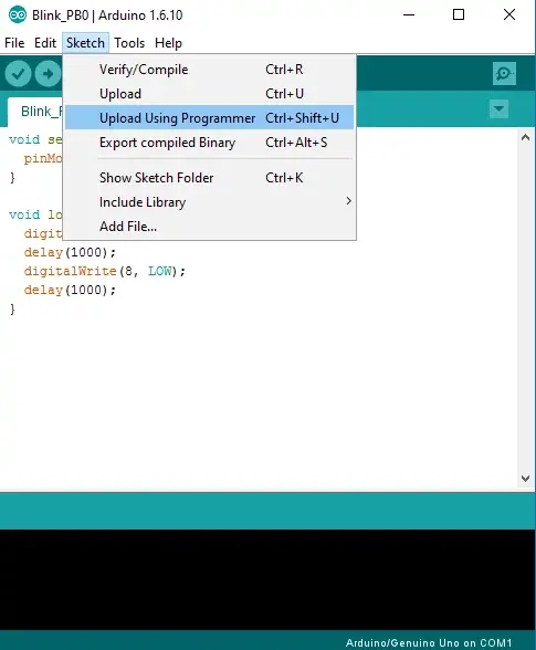
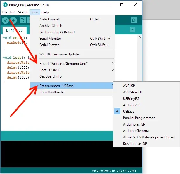
Setup the Arduino IDE by selecting the board to be the “UNO” and then choose the programmer you are using. In our case we are using a USBASP compatible programmer (Figure 7). Then go to Sketch -> Upload Using Programmer (Figure 8). This should flash the ATmega328P on the AVR_Tag-Connect example board and start flashing the LED! See Figure 9 for blinking goodness.
Final Steps
Now just power up the board and you should have a nice blinking LED!

Using this example – engineers, designers, and makers should be able to easily add the Tag-Connect connector to their AVR projects and Arduino based designs. This should help lower the cost of products by reducing BOM costs and reducing the time to program the device.
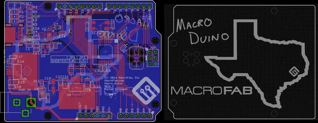
I’ve made a “Macro_Duino” which is an Arduino compatible board that uses Tag-Connect and USB Type-C (See Figure 11). I will have an article in a month or so that will feature this board.