Hail to the signal switcher! On this episode, Parker wraps up his prep work for the Extra-Life Charity stream and Stephen discusses switching signals.
Why is estimating a projects completion time feel like it takes more work then the actual project? Estimating Project Time, the quest of management.
Our Spider-sense is tingling... OH that is actually a man-made zombie spider crawling up my leg. Who thought that would be a good idea? WHO!?!
Parker is an Electrical Engineer with backgrounds in Embedded System Design and Digital Signal Processing. He got his start in 2005 by hacking Nintendo consoles into portable gaming units. The following year he designed and produced an Atari 2600 video mod to allow the Atari to display a crisp, RF fuzz free picture on newer TVs. Over a thousand Atari video mods where produced by Parker from 2006 to 2011 and the mod is still made by other enthusiasts in the Atari community.
In 2006, Parker enrolled at The University of Texas at Austin as a Petroleum Engineer. After realizing electronics was his passion he switched majors in 2007 to Electrical and Computer Engineering. Following his previous background in making the Atari 2600 video mod, Parker decided to take more board layout classes and circuit design classes. Other areas of study include robotics, microcontroller theory and design, FPGA development with VHDL and Verilog, and image and signal processing with DSPs. In 2010, Parker won a Ti sponsored Launchpad programming and design contest that was held by the IEEE CS chapter at the University. Parker graduated with a BS in Electrical and Computer Engineering in the Spring of 2012.
In the Summer of 2012, Parker was hired on as an Electrical Engineer at Dynamic Perception to design and prototype new electronic products. Here, Parker learned about full product development cycles and honed his board layout skills. Seeing the difficulties in managing operations and FCC/CE compliance testing, Parker thought there had to be a better way for small electronic companies to get their product out in customer's hands.
Parker also runs the blog, longhornengineer.com, where he posts his personal projects, technical guides, and appnotes about board layout design and components.
Stephen Kraig began his electronics career by building musical oriented circuits in 2003. Stephen is an avid guitar player and, in his down time, manufactures audio electronics including guitar amplifiers, pedals, and pro audio gear. Stephen graduated with a BS in Electrical Engineering from Texas A&M University.
Special thanks to whixr over at Tymkrs for the intro and outro!
Welcome to the macro fab engineering podcast. We are your host, Stephen Craig,
and perky Dolman.
This is episode 282.
So last week, we had a huge topic about through hole components. One thing I wanted to bring up, but we were already in like an hour long on just talking about through whole, like parts and layout considerations. But it's SMT connector considerations. Because one of the one of the things that we tell our customers all the time is more through hole, not more through all. Yeah, more service mounts, if possible, if possible, convert as much as you can to surface mount because it is less expensive to assemble. And you if you can cutting out the through whole process makes your product just much less expensive to make. But there are some problems I guess when switching to surface mount for connectors, connectors is like one of those last strongholds of through hole. I feel like in products.
Well, I mean, there's the mechanical advantage, right?
Yeah, well, that's the thing. It's it's all about mechanical retention. When you have a surface mount part, you're relying on basically the bond between the copper and the adhesive that's on the FR for. Whereas through hold, you have the entire via that's plated to the FR four and both sides of the adhesive trying to yank itself out of the entire board.
Especially if especially if you have IPC class three soldering on on through whole stuff. That means you're going to have basically through the entire barrel worth of solder and fill it's on sides.
On both sides. Yeah, yeah,
it's strong.
Yeah, yes, peel strength. The peel strength of the SMT pads is what you only are really relying on with SMD SMT connectors. But that might not be a concern, because it might be a connector that is only used during assembly. So like it's inside the the unit like an FFC cable, something like that. Those are always I won't say that I've seen through hole FFC connectors, but majority of them are going to be surface mount. Like basically it's how many insertions is that connector going to have to withstand through its lifecycle?
Also, which direction is the force coming from on that? Yeah,
if it's going into the board, only, then you're probably okay. Going with a surface mount but if it's being yanked off the board, especially with a cable assembly, you might want to go with a through hole.
Yeah, that might work for you in your lab, but the second Baba out in the field has to pull a cable assembly off like that SMD connectors come and
ride off. Yes. It's also the price difference where I've noticed is SMT for the same connector. For some reason SMT connectors cost more. I don't know if that's because they just cost more in general or is it's they're not as many manufactured of the same connector. I'm going to bet you it's that is there's more of a through hole of a connector being built than a surface mount connector. That'd be my gut. Yep. Now, there's also other rules to this as well. Like USB connectors, a lot of USB connectors are surface mount but then they have solder lugs. And if you get the right kind of connector, you can also do what's called paste and pad which is where they inject the paste into the through hole, which is which works for like USB micro USB type C connectors. You actually will see that on products where if you look at the board, and then like the the lug doesn't go all the way through the board. It kind of goes halfway through and you and they don't have fillets around lugs. It just looks like solder being looks like surface mount solder because it is,
you know, I got a quick question for you. And this This is in relation. Well, any contract manufacturer is going to handle this slightly different. But what if I'm an engineer and I'm about to send you a document package and I choose one of those SMD USB that has surface mount legs, but through hole mechanical pieces. Do I consider that a through hole part or an SMD? Part?
Depends if you're if it needs that secondary assembly. So if you if you can get away with paste in hole, that its surface mount all the way, but the moment you go, okay, like, if you don't design the pad, right, basically it has to like give us a round hole for the lug, then that's getting hands on. Yeah, get the hands off because you have to feed a lot of solder into it, there's no that you can't put enough paste in there to get a good mechanical connection. Right?
I think I think the general rule of thumb is treat those as through hole if there is a through hole leg treated as through hole. And you'll be pleasantly surprised if you get charged SMD price for assembly on it.
Correct? Correct. Now, there's some big things been some of these things I've been experimenting with, in basically switching everything to SMT. I've been experimenting a lot with pinball related stuff, because pinball boards have lots of through hole connectors because you have big chunky connectors that have to carry a lot of current. And they are mounted like on the back box to kind of like to the operators are like leaning over and then grabbing just the wiring harness and then yanking on the board. So you want as much strength as possible. But I have been experimenting with through hole with SMT to replace those because they would be much cheaper. Like I'm talking like I could save like 10 to 15 bucks per unit
in just a mark cost or assembly cost. Okay,
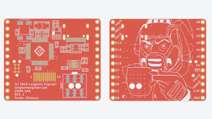
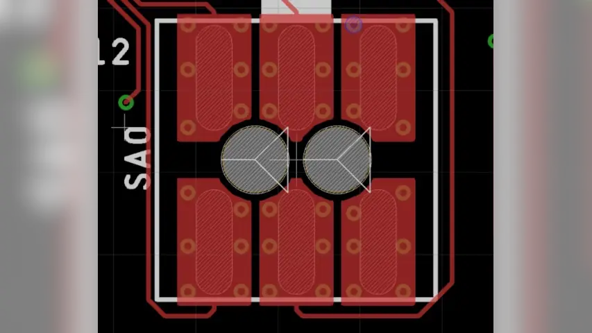
some of the cost. And the parts for the those components are about the same. So SMT versions are about the same as the through hole. So it's a wash with the part cost so what well my first big experiments was with the the Doom shitty add on for DEF CON about two years ago. Right? Yeah, and so the this is for hashtag badge life. And so I made a a add on for badges that had a screen on it and you could basically load a GIF into the screen and so you had a little tiny screen on your badge that could do whatever you wanted to do. And it was called the Doom should be out on because it was loaded with basically almost like a tema Gottschee Doom character because like you could like it was very you couldn't like feed it or anything like a Gottschee would normally be like but like you could like send it a damage points and so he get like more bloody and get angry and he also had a an angry face too so you can get more angry or more damaged and then there was like a god mode you can enable his eyes glow yellow Yes, eyes will glow yellow. So for that though, I need like it's Bill materials was like insane because I like it had like a beefy Mike had a microcontroller more powerful than most badges. To begin with how to run a really high resolution screen is a really high DPI screen. I think it was like 200 DPI screen is one inch by one inch, or 240 something like that. And everything was super compact. And so I needed to go to a surface mount connector. And those connectors were two by three 2.54 millimeter connectors, kind of like an Arduino header for ISP programming. And so I did experiment with doing surface mount ones of those kind of pin headers. And what I did is I made the landing pads a lot larger than what the manufacturer called out for like almost like three or four times as big. And then I put the same pad on the backside of the board. So I had two surface mount pads, and then I put vias around the perimeter of each pin. I'll put a screenshot up on the on the podcast so so people can visualize that. But basically I via stitch like how you would do for grounding. Same concept, except it was two pads back the back and via stretched around it. And then reflow the component on that. And it reflowed fine didn't have any problem with thermal syncing or anything like that. And the and then I basically destructively tested this by putting the pin header in a board and a Like breadboard and then twisting the PCB, and it would shear the solder before it would shear the pads off. So, in my mind, that is that's good enough,
like it's not as good as it used up the the peel strength, the peel
strength. Yeah, so it's not as strong as a through hole connector because the through hole, you basically would have to shear the pin itself and twist it. And actually, you'd have to do that for, you know, six connect six pins in this case. But it was good enough where we didn't have a single failure at DEF CON, doing this method. And at DEF CON, everyone is drunk and dancing and stuff. So
yeah, and this, this add ons just hanging out on badges, you know,
it's not just on the badge, the badge is wiggling around. But it's like hanging off the badge to in free space,
because it's, its main point of contact is the connector. That's the only,
that's the only point of contact. Well, yeah, and it's not a lightweight bag of add on either because it's got a screen on it. I was just, I was just really happy about that method, I want to apply that to pinball, and see how well it works. I've been experimenting with that, and I built a board for it. I just need to be able to put it into a pinball machine. And actually, I want to test it in real life before I like roll that into production. And have operators like, you know, beat on it. So,
you know, I, I have a client right now that ran into that issue with a board that they were that they were doing that they have a 90 degree surface mount header. And so they have one board 90 degrees to another and it's kind of flapping around in the breeze and and somebody hid it inside of a case and it ripped all the pads. And, and it was a mistake, but it was also like, huh, we need a solution to that. And so I might, I might actually suggest this as a it works
really well. Yeah, it's still not as good as a through hole. But it's I mean, you're, you have you're sharing the solder. And so at least when it cheers the shot solder, you can still go back and fix it. It's not like it rips the pads off, which is really hard to fix.
So So I guess I guess the two things that are potential downsides to it. And they're they're fairly minor if he asked me, not all connectors are going to have extra room for you to put all those vias in there. So you, you might have to go with smaller vias, which is a pain in the butt. And then the other thing is, if you're creating these via, like in three dimensional space, these via fences around each pin, you're losing a ton of routing space, in your PCB across all your layers. So that kind of sucks. Yeah,
anything around the connector is basically you got to treat your connector as a through hole connector.
Yeah, but like, yeah, really big through hole connector? Yeah, really big
throw connector. Yeah. But hey, all in the name of less expensive assembly?
Oh, I mean, if you can get away with it, okay. There's, there's the difference between like, saving money by going to a different thing. Or doing what I call free work. Like if you can, if you can, like hack a PCB. The only cost is the development cost, right? Like, just moving things around doesn't end up costing anything in that PCB. So you got a free fix there. Yes, like, okay, at work, most of our boards are two board designs. So I developed what I call book matching. So our boards go together, face to face. So when we penalize them, we open them up and put them side by side such that all of our surface mount go on one side, and all of our through hole fit in from the other side. And therefore we get one pass through our pick and place and one through our selective solder, and then the user, not the user, our assemblers break them apart, and then they fold them together and you have a product. And it's that was one of those free things. Just think about how where all the parts go and it saves double sided assembly or crazy through hole stuff. And on that BookMatch when you open it up anything that's on the inside, we typically use surface mount parts, so it still adds to the or maintains the one side through hole processing.
That's good. I never You never told me that. It's a cool idea. No wonder that y'all you want to control your your panelization
Oh, yeah, we're real strict with our panels. Yeah. Yeah, we try. We didn't used to do this, but we try to, as much as possible put a full product on a panel. That would be that would mean multiple PCBs if if there are multiple PCBs on us. And, in fact, I just redesigned a one of our products and took it from. I can't remember it will Okay, so it was two different PCB arrays, two different passes through the pick and place and one pass through the selective solder. And I redesigned it entirely for one PCB array, one pass through pick and place in one pass through selective solder. Nice. And just by doing the BookMatch and moving parts around, and basically,
you set the panel for optimized assembly.
Yeah, that's like a heavy, heavy DFM. But also, we have enough Oh, 402 feeders on our machine now. Whereas, like, whole thing, oh, 402 everything I can get away with, oh, 402 I'm doing it, you know, nice. Because I guess, I mean, when you start to get like, our stuff is getting way more dense, we're putting way more features in our products than we ever have. And the size of the product is not getting any bigger. So it's like well, parts gotta get smaller. Cool. So I got an update to my plastic actuator. I've been talking about this for a little while now. So they the plastic actuators. My little button thing that I've been designing for a few months now
is injection molding and all that good stuff.
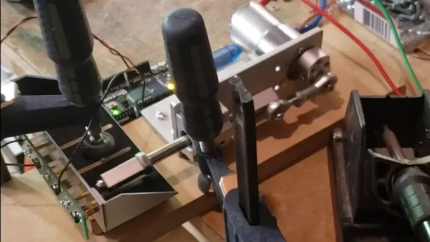
So I showed everyone my my button masher 9000 which was a solenoid based test rig thing, which, when I got it all fired up and working it functioned. But I wasn't super happy with it because it was just too slow. I had to I had to PWM the solenoids. And the the ones I purchased, they had a rated press force. And they just were not what they said they were at all. So I had to overload them. And because of that they overheated. So I had to do like I had to I had to small duty cycle them and stuff. And this is garbage. So I got a linear actuator just decided to beat the hell out of the buttons with a with a linear actuator. I didn't go that route at first because I didn't want to damage the buttons. I didn't want to like over overthrow that. And with the with a solenoid I was going to put a small like rubber piece at the end such that I could smoothly press them. But I ended up just fine tuning my test rig such that I could get it just perfectly where the linear actuator would press the button.
Yeah, the just before Ender stroke is just enough. Yeah,
yeah. Well, and that's just the thing, okay, so the the actuator I got has a half millimeter stroke does not have millimeter, half inch stroke, I was gonna say half millimeters.
It's pretty small. I
mean, that honestly, that would be awesome. I wish it was cuz that would be better. But ya know, it has a half inch stroke on it. But I only need to press 16 thousandths of an inch. So like 98% of its travel, it's not doing any useful work, right. But that's just the whole thing. Like it's way easier to overthrow 16 1000s of an inch. But just I don't know, careful tuning and positioning of things. I got it working. So the the actuator got its 12 volt DC and it runs 300 rpm. And so I just cranked it wide open. And I wrote an Arduino sketch that just basically counts the number of times that it it detects the button being pressed. And I'm up to 420,000 button presses now with no failures, which, hey, like that's well beyond what I'm already happy with some some of our previous buttons that I'm designing this to replace, we had been seeing failures in the low 10 1000s. And so like I'm already way, way, way beyond what I'm what I'm looking for there. So the goal is to whichever one comes first a million button presses or failure. It's what I'm what I'm going for here. And the so the cool thing is, I've been occasionally stopping the test rig and just pressing the button by hand to see if it feels any different. And and it certainly does have a little bit more of a worn in feel. But nothing I would say is is significantly different enough to that, like a customer would be upset with it, you know, and there's no way on earth that any of our customers are ever going to press something 420,000 times across the lifespan of this thing so I'm already way past what what is necessary, but I'm just gonna keep going with it. At the same time, this is only the first actuator I'm going to test a handful of these but I'm I'm thrilled with how that worked already. And And okay, so to be honest, I think I'm actually well past 420,000 presses. I'm at 420 1000 Arduino presses. And I realized that I think my sketch that I wrote would miss some presses. Occasionally. That's one of the reasons why I wanted to originally go with a solenoid because the Arduino could tell the solenoid and then report back, if it actually got a press, then I get, then I'd have a feedback loop. But with this, I don't really have that. I'm just counting presses and seeing if it ever fails. And the reason why I think it was missing pulses is because I had a handful of serial prints in there, because I was just having it print out the number of presses as it counts up. But I had it also print a handful of other things. And I completely forgot that in Arduino land, like those functions take an enormous amount of clock cycles to do, like, Arduino is not particularly efficient. And at 300 RPM, that's five times a second. So I have a fifth of a second to detect my pulse, and do all these serial prints. I think that it was, on occasion rolling over and not detecting upon,
you're not using the interrupt. No, hell no.
I didn't, I didn't want to write I didn't want to go and write an interrupt I probably should have. But I ended up just getting rid of a couple serial prints. And because I had some that were just making it easier to read in the monitor the serial monitor. So it's just like, I'll just get rid of those. And now it's detecting every pulse. So 420 is what are doing it was reported, I bet you it's probably more like 430, or something like that.
Yeah. Because I've been working on some fixturing stuff at work and test fixtures. And that's why I brought up the interrupt thing is, so I have some test fixtures, that operators are plugging the D UTS device under tests into it. And I need to let the computer know that's running Python scripts that a user has interacted with that the UT EXO so I have a microcontroller inside there that's actually monitoring on an interrupt those switches. And then it's what does it six that stuff into a mailbox. And then when the computer goes, Hey, it actually the computer the my controllers running a Skippy interpreter, so I can talk to my my fixtures the same way I talked to my multimeters and all that stuff in my power supplies, I can just use Skippy, which is the was it was that same for again, it's SCPI, which is Standard Commands for Programmable instruments. So that same kind of structure I can use for my my relay boxes and all that stuff. So when the Python code goes, Hey, I need to know what's going on with the switches. It just says, it just says SW question mark. And then the are the microcontroller inside the box goes, Ah, I know what that means, grabs the mailbox, sends it out and then zeroes out the mailbox. So that way I don't have to have I don't have to have the computer the Python code just constantly pulling the switches. So that the low level does the interrupt on that stuff and manages the low level button presses. And the high level stuff just has to go. Okay was a button press since the last time I checked. makes it so you don't miss anything. Yeah,
yeah. That's that's a more proper way of
I like I like how it's proper is the right way to do it, though.
I mean, it's a it's a lot more logical as opposed to just relying on your main loop speed to be like, Hey, Did something change? I don't know. Let's go another loop and find out.
Yeah, go go. No loop. Speaking of Python, though, is Dan, who's a one of our lead developers here at Mac fab showed me this module for Python called ice cream. Do not know why it's called ice cream. So what do you think this module does? That's called ice cream?
I have no clue.
So it's a module that makes debugging through print functions better? Because I know everyone here so everyone should get this is what you're saying. For Python? Yes. For serial prints in Python, like because it's going to print to just your command line. This is I've been starting to use it. It makes your code a lot better and a lot easier to read. So what it does is it automatically does verbose print statements in Python. So usually when you just say print x, it was just, it just prints the value of x. But the, what's been assigned to the problem is, if you have a lot of print x, and then print y, etc, etc, you don't know what those numbers mean in your, in your console logs. And so you usually would go, print x equals dot format x, that gets old after doing that, for every single thing you want to print. The thing is now you can just do IC X, and they will print x equals this, like, it'll automatically does the verbose stuff for you. Mm hmm. And then also thing is, it's easily disabled. Like, you just have to have like, at the beginning of your script, just put, like, disable I see, or ice cream, and boom, done. That's nice. So instead of having to go through in like, either wrap a, what I do is wrap an if statement. Basically, if debug is true, print this. And if not debug don't print it. Right. That's nice. I have to do that for every single thing I print in my scripts. Now. I don't have to do that anymore. Ah, this is awesome library.
It's funny, because because that's exactly what I was trying to do on a very small scale in my Arduino sketch is just have it print out something that just wasn't a value on the screen. And just like, exactly the flowing values, right? Yeah,
this is exact, like, this is an awesome module. And I I wonder why something like this didn't exist before. Huh? Yeah, that's cool. But, um,
why don't I just go to Google and type in ice cream? Python.
I'll put the link in the show notes. But it's, uh, it's do not use print for debugging in Python anymore. A redefine print function for debugging in Python. I Christopher Tao.
Yeah, yeah. And they give they give an example right at the beginning, where they're just saying, like, print some values, and that's all you're gonna get is just values. And that's fine. If you only have one or two, you know,
yes. But when you have like an entire script for testing, validation, use proper logging, and printing his proper logging Chris?
Are you have you have those random print functions that are you know, if you're trying to figure out debug your code and figure out like, why you did or did not get to a function, and you just have it pop up in the screen, like, I'm in the function or something? Yeah.
Print here, here. Also, my my air, like, if it's not supposed to get there, it just says print fuck.
That's great. That's cool. I really do need to get into Python one of these days, and just start digging around just because it's so useful. It's so useful from a manufacturing engineers standpoint. Exactly. Like I don't have a lot of things that I would want outside of that realm. But doing test fixturing and talking with with, with meters and things like that, like I really didn't need to learn it.
The big thing is, think about anything that you do that is tedious. And repetitive. You can make Python and stuff make. Take that load off.
Oh, yeah, yeah, yeah, I know, I have a Text Parsing task that it's more than just dumping text in a in a separate text file. It would be great to have something that I could have one of my operators input a few variables in, based off of what the run was. And it would automatically adjust a text file based off of that, which Python would be very happy to get that done. Yeah.
You could either easily do that in a script, or you can even further and make a little GUI.
Well, again, the GUI would be the GUI would be really cool.
Yeah, we should do a little love. Do a little demo at like a, a Mac fab after dark some time and actually write this code for you. Oh, that'd be fun. That'd be like do some some like, Intro to Python for hardware engineers.
Oh, yeah. Well, I mean, it would be an intro for me. Really?
Yeah. Well, base like installing like an IDE and Python on Windows. Oh, yeah. Getting that stuff running. And then like, let's make a little GUI that you type in some numbers. I basically
have a full Excel sheet that that is that good. that does all everything automatically for you. And then it just spits out the lines of text that need to get entered in. So really all I need is that Excel sheet distilled into Python code. And then the last function of taking the text file and putting it exactly where it needs to be. Which, what's funny is, I have this this text file that can be anywhere from like, a few kilobytes all the way up to 250 megabytes. And what's nice about it is it there's the word absolute in this text file. And it always only occurs one time. And it always occurs in the same place. And I always know that my code needs to happen directly after the word absolute. And that's it. So it's super easy, right? You got it? Yeah. Yeah, let's play in that. I think that I think that sounds like fun. It's been a while since we've done the an after hours.
Yeah, but to do that, what the planet, we should see what people are feeling timewise in like the Slack channel, if anyone's actually interested in that.
Oh, that'd be fun. Yeah, I think we should also do a, like a board design or something like that
in an after? Oh, yeah, we need to do that one time.
That would be really fun. And just have people critique it the entire time. Or Twitch lays out a board, right? Something like that. Now,
imagine it because that's, that's based off the
TwitchPlaysPokemon
TwitchPlaysPokemon phenomenon from like, what was it three years ago now? Four years? Anyways? The I'm trying to imagine how that would, you'd have to have a text based only entry. So you could technically do an Ico
I was gonna say that sounds eagerly. That sounds brutal at the same time,
so I wouldn't imagine you would give it a schematic already.
Yeah. I see that I see the gears turning and Parker said,
Yeah, cuz I've actually looked at the code that makes that TwitchPlaysPokemon thing work. It's pretty easy to make it do whatever.
You can adapt it. Yeah.
Huh. Cool. Well, so what kind of if we did Twitch Plays Eagle layout? What board would we have designed? I would think just starting with a simple board, like yeah, maybe a coin cell battery, a couple resistors an LED?
Oh, it would have to be a few parts. Just to give it a try. I think like, most difficult you could go is like an Arduino. Now would be pretty complicated. It would be but that's why I'm saying like that's like top.
And then what you would do is it would have to pass DRC and no ratlines at the end. And that's when you would be considered done. The moment those two those two things exist, then it just goes done a freezes design and then immediately prints it on macro fab immediately orders it immediately orders to the API.
Yeah, it sends it to Parker for testing.
ends up being like a frickin like 15 by 15 inch board in 1000. Dock. One little LED on it. Yeah. And it has a three mil trace that connects every everything together. Hmm. I'd like this idea. We should do it. You know,
I write this down. This is this is somewhat ridiculous. But I've always wanted to take a board. And, and make like, I don't know, let's say let's say six layers, do six layers with blind and buried vias in it. And take one trace started at one corner and consume an entire layer in the most efficient way. So like, have like, I don't know, let's say a 10th. Out trace. And following DRC rules and everything, cover every inch of that board with a snake trace. And then plop down one layer and come and do an entire the entire next layer and do that all the way across the board. And I have no idea why I want to do that. It just sounds like fun for some reason, like it would serve zero purpose. Other than like, how many miles of trace Could you put on like 100 millimeter by 100 millimeter board? I'd probably not even a mile. But how many numbers of traces can you do?
You can easily calculate that.
I don't know like what's the most well now we're getting into mathematics like you'd have to like what's the best packing algorithm you can to, you know, rapid tracer, and there's a fractal that gets into that. That that's like the best choice path you can take to fill the most area of something. I don't remember what that one is called, it ends up looking like Castle turrets all over the place. It probably ended up being a really awful antenna, right? Or a really awesome one. Yeah, well, one or the other. Yeah, yeah. So I've got an interesting circuit that I'm working on at work. And this brings up something that for my industry, not just audio, but But specifically, industry that uses plus minus voltage in as your as your power supply. I run into this issue a lot. In fact, a few months ago, I was talking about the need for a negative voltage input, negative voltage output, switch mode power supply, which you know, at first you think about that you're like, okay, cool. Yeah, just go find one. Yeah, good luck, they just don't exist, because like, the world just doesn't really use bipolar supplies, as much as they do unipolar positive supplies. So I'm kind of running into that same situation, right, now, I've got a circuit that will, okay, let me back up, I've got an entire module that I'm in the process of designing, that's a pretty thirsty one. So the the, it's very power hungry. And the thing that we're trying to take into account with this is, most people the power supplies they purchased for their case, are just barely good enough for the case. And if we design a really power hungry module, then we can cause problems with the startup of other modules. In the case, if RS is just acting like a, an extreme load right from the get go. So our solution to this, that we're wanting to implement is a time delay startup on art module. So basically, when someone flips the switch on their power supply, all of their modules comes up, RS waits a second or two, and then starts to come up. And not only that we have, we can control all of our power supplies within our module and do all of our separate enables and things like that. So this sounds like a great situation for a load switch, right? Like a like a PRN channel load switch kind of thing. What's and, and, of course, this can be done in a discreet manner, we can just throw some competitors at it, some moss, fats and things like that. But I was wanting to see, what would be really, really super ideal is if there was an integrated circuit that handled power load switching with a time delay for bipolar inputs. And it's just like not that doesn't exist. In fact, I noticed I was I was searching earlier today for it. And there was like a Texas Instruments forum where someone was asking for something very similar. In fact, they were just asking for a load switch for negative supplies, and multiple ti engineers were chiming in being like, yeah, I don't think we have that. In fact, I've never even heard of that.
If ti doesn't have
it doesn't exist. Basically, that's like I took that as as kind of truth there because I started looking through TI and a handful of others. And not really, it really doesn't exist. And the funny thing is, it's sort of the same as a high high as a high side positive switch, it's just you changing the transistor types and doing some different logic. The biggest thing that I want to do with this is I want one control signal. So I want it such that there's a time delay, and then that time delay triggers the load switch for both of the positive and the negative negative rail, then after that, there's a secondary delay. And that secondary delay sends control signals to all of my power supply enable lines, and then I can bring my power supplies up. So it's two stage because what I want to do is I'm trickle charging up all my input capacitance on my on my module, so it doesn't act like a huge load all at the beginning. And that's that first initial delay that first initial delay, charges up all the my huge bulk capacitance on the front end. And then as soon as I throw my control signals to all of my enables, they consume power from my capacitors that are that are been trickle charged as opposed to acting like a giant load all of a sudden on the the main case power supply. So hopefully you want to it's kind of soft.
You might want to look into pmics Power manage power management, integrated circuits. Ti has got a lot of them. I think they make bipolar ones of those. That might be what you need.
Well, I was looking at T eyes offerings in the whole power world today. And I didn't find anything that that really stood out to me if anyone is aware of it. Let me know of something that could work in this way I can, like I said, I can always implement it in discrete and the the, the, the, the whole situation here is, if I were to have one IC that can handle this, it would have to be cheaper than the discrete solution. Mm hmm. So that's that also kind of sucks because I C's are expensive right now. But But yeah, that I know, I can pull it off. The one thing that I'm looking at that that could be kind of cool is instead of using MOSFET, as my load switches, potentially using SSRS, because with an SSR, I could control them both the positive and the negative with one control signal. And I wouldn't have to do logic switching to because it's super annoying to have to control a negative load switch with a positive signal, you have to do some transistor goofiness to.
So translate things couldn't you use? Let's say you have plus minus 12 volts here, whatever, you had a zero volt 12 volt and 24 volt rail.
I mean, I don't I don't have that.
Well, yeah, you could, you could easily have that. It's still the
same. You want to shift the grounds on things or shift your grant. Oh, yeah,
yeah. Yeah. Shift your reference up. kilovolts. And then you could use an off shelf P MCI. That does all that.
Uh, I'd have to look into that. Maybe. Because like, I still rely on ground being grounded in the case. And this thing is being connected to a bunch of other things that I have no clue about. And and that PMC I would not make that isolated. So I don't think that that would particularly work. You'd have to isolate everything to make that that work. Right. Yeah. So I like this idea. That's
cool. I wonder if they have a bipolar P. MCI. Or anyone does? That might be the right. Might be the right term. You need to start Googling though. Yeah, Tmic? I mean,
yeah. Especially if it's all all in one kind of solution. I do like the the, the thought of an SSR. Although the SSRS on, if you look at, you know, inexpensive board, Mount SSRS. They're great, but they usually don't have particularly high current ratings. So I think that's where I'd have to spend some more money to get a higher current rating. And then at that point, like, you know, you're blowing 20 cent transistors out the water will actually be much, much cheaper than 20 cents. So I think I'm gonna have to end up going with a transistor solution even though I really would rather not, I'd love to have like an all in one package. So if anyone knows about that hit me up in Slack.
Well, I'm looking forward to what the solution becomes. Yeah, well, I
kind of already have been I've gotten an LT spice doing some some stuff fancy stuff. But it but it's not. It's it's not polished yet. It's doing stuff. It's just not polished. I could switch a load let's put it that way.
That's the first step. Yeah. Okay. Tasty chips time. And this is a these are two not unfortunately, they're not chips. I don't think they're ever since we brought back tasty chips. Not a single time. It's been a chip yet. Not yet. Not yet. So the Keystone 9081 These are going to be so like, like, these components when we like people are gonna look at me like, Oh, it's so fancy about those. It's the application of these that makes them awesome. So the Keystone 9081 is a plastic standoff. And it was like, oh, yeah, standoffs, right for mounting holes, but this one has double sided sticky foam on it. So when you are doing prototyping, and are throwing a PCB into a rackmount enclosure, or any kind of closure, and you don't have time as an engineer to like do your mechanical design correctly, or you don't want to deal with drilling holes into in like getting an aluminum all over your shop floor. Pop those little snaps into your board. Take the foam tape off the low backer Let's plop the board down, done.
You know, I would I would totally use these in a situation where gravity is is with you. Gravity is your friend, like Yeah, boards hanging upside down, you know, that's probably not a good good thing but like if it's if it's flat against Yeah, they like these things are awesome dude I love just go into Keystone electronics website and just browsing all of this stuff because they have so many unique
concepts and ideas like they like a lot of their a lot of their stuff are things where it's just like I look at it and then I can see the product around what they have exactly. I saw these plastic standoffs and I'm like, Oh, I know what these are awesome for. But they have so many products like that, like Keystone 7693, which is a screwed a through hole screw terminal. But it's a it's a it's raised off the board. And so that when you put your let's say you put your ring terminal on it, it keeps it isolated from the board. And they're beefy, like their Ford giant lugs that go into the board. So there's no way it's going to rip off.
You know, another thing that is super minor, but like I just love it, they they have a good relationship, I guess with Mouser such that, like if you go to Keystone electronics website, they have a four digit number for all of their products. If you go to Mouser and you just type in that four digit number it takes you right to that part. You don't have to have this like 15 digit craziness number anything like that. In one of my amps right now, I am using a handful of Keystone parts. Pull up one right now the 7833 which is they have vertical standing quick disconnect PCB mounts that are all in a in like a you could buy them by however many positions. So I buy them based off of my transformer tap. So if I have a three position transformer tackle by the triple one or a double one for dual tap, and then I slot flag terminals into them, and they're awesome. These things are killer.
Yeah, Keystone sponsor the podcast, please. Also, if
you're if you're an electrical engineer that doesn't want to learn or deal a lot with hardware or mechanical engineering stuff, like you Keystone electronics cells, like em three screws, and on now Yeah, and you can just pick those up for whatever hobby project you're doing. And so
yeah, yeah, save on shipping cost.
They also have a really nice to 220 Mica mounting kit. So if you want to pull a to 222 chassis or something like that. It comes with all the mounting hardware, but plus and isolating shoulder washer that goes through the tab and stuff. I've used those a bunch. Those are nice. I mean, it ends up being like $3 for a mounting kit. But if you're doing hobby stuff, most of that must have done that doesn't matter.
Yeah. So Casey eight, a PF from switched. Twitch chat, says, Steven, you probably want a hot swap controller instead of a load switch and has a link to an analog. Actually, it's a Linear Technology part. It's LT 4220 which is 16.5 volts.
I was looking at hotswap controllers before earlier today, but yeah, I didn't see this one. Look at that. It will do hotswap controller for positive and negative supplies. Wow, look at that. It does supply tracking and it totally covers the entire range that I'm looking at. Ooh, does it do current limiting as well?
current limit with fullback ooh,
oh, fullback. I like that.
Okay, and it's actually very similar application, because it's for a live backplane which is kind of similar what you're doing.
Okay, so yeah, what's actually kind of cool. Yeah. What's what's really cool about that is none of these, none of no modular unit is ever supposed to be hot flopped ever. Mainly because the connector itself you can't guarantee how somebody plugs it in. So which supplier is going to get power first or is grounded going to get power first or whatever. But a hotswap controller can can help prevent that, you know, so, ah, thanks. I'm gonna have to look at this. It's linear. So it's probably expensive, but we'll
Yeah, that's it.
Well, that's true. Yeah. Let me let me see this. Is the is this cheaper than a Oh?
$7 in quantity. Yeah.
Okay, I'm still gonna look at it because it goes, it could be cool. This is going on a unexpensive module that's that's somewhat flagship
it is in quantity in buying a real, it's $4.87, which actually isn't that bad.
Yeah, but a few resistors and transistors is a lot less not bad.
But this does more than what that can do.
That's true. That is that is totally true. This actually does. From what I'm looking at, it might. Let's see here. Oh, and it has a timing pin on it. Oh, that's cool. That's real cool. Okay, I'm totally gonna read through this whole datasheet
or not, now we got finished podcast. No, right. Now, come
on, let's do it live. A live reading of the LT for two to zero.
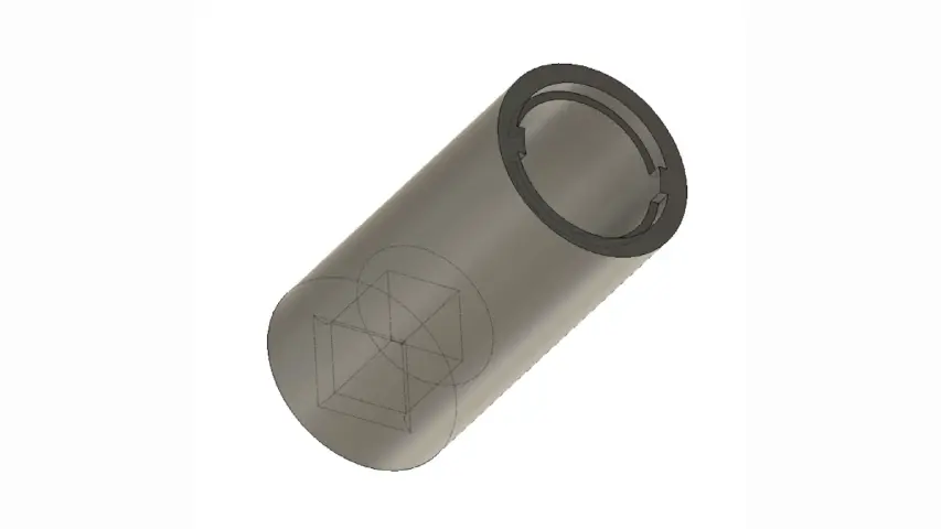
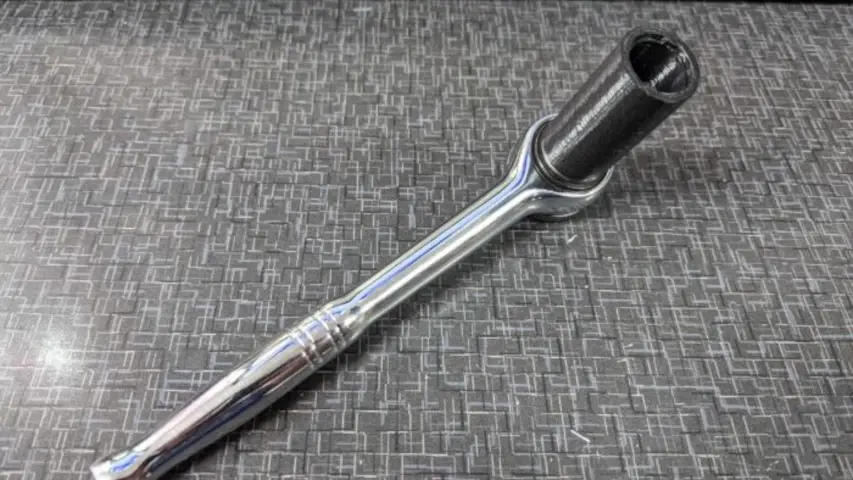
Well, to prevent our listeners from falling asleep, we'll move on. So I was looking at a building all these rackmount test equipment stuff for work. And I needed to install a bunch of banana jacks. And I don't know if you remember from back in the day, Steven, we built the reload Pro, which is one right there on my desk. And we had to install the banana jacks on those. And we had some tools that were like hand tools that kind of like basically the the nut of the banana Jacks have two teeth that go into into it. It's not a hex, like a normal nut would be it's it's circular with two teeth that get cut out on it. And so you need to have a tool that's got two cogs to engage it. And so you could turn it and actually get it tight on the panel so it doesn't spin and rattle loose. And so I actually went through my drawer at work and like, oh, where is that tool? It's not there. That was like eight years ago at this point. So that tool is long gone. And so I started looking up. You know, buying that tool. They're like 80 bucks for a piece of steel around piece of tube that's got two notches in it. Yeah. $80. So I was like, okay, someone's got to like, design that tool. So you can 3d print it. Right. Couldn't find one. So I designed one.
Yeah. Sounds like it sounds like it sounds like a you problem.
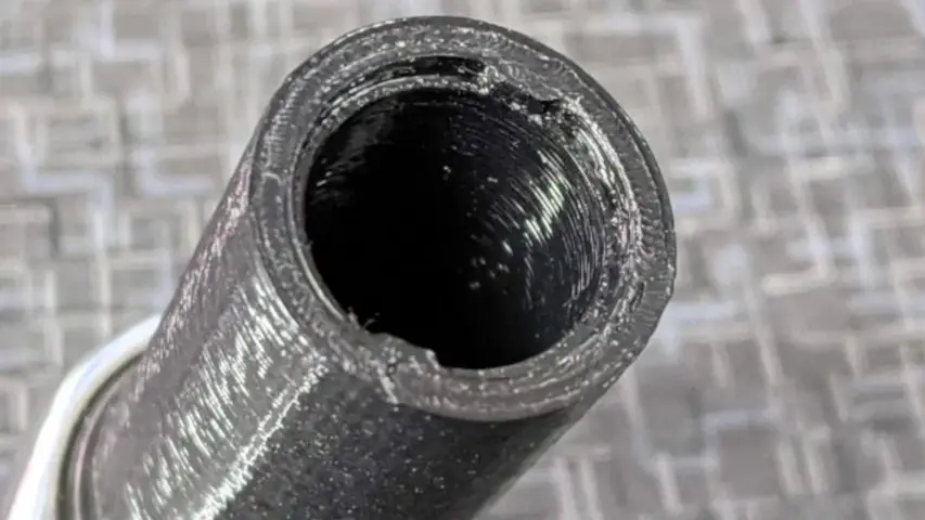
Yeah. Sounds like a you problem. So I designed one. And actually, I popped it off the printer right before the podcast. So I'll post the pictures, but you can see little little cogs. So so so it looks like a ratchet with a yes, because I actually made put a quarter drive on the back. So I can put it on a ratchet. Because even the ones that you can buy for $80 are still by hand, they have to look a little neural on the back. So you could spin it. I'm like, No, I want it on a ratchet. So I can put a i My electric ratchet on it and just spin it tight. Yeah. Nice. So that is I will share that STL because it is a shame that no one has done that yet. Hmm. Now, how long will this tool last? I have no idea because those cogs are really small. How long does it need to last? Exactly. Because it took 15 minutes to print. I can just print a ton of them. I'll post that STL it's pictures on the podcast notes.
I dig it. That's cool. I actually I ran into a situation not long after I came to WMD where we needed a tool like that
craft lab that we 3d printed the one we used to assemble those reload pros. It lasted a few minutes for yes, yeah, it lasted a few minutes and then we broke down and bought some steel ones. But this is made out of polycarbonate so it might last longer might and actually I should try printing this with my new resin, the strong X resin on my resin printer.
If that doesn't work, send me some steel and I'll mail you one
that might be a little hard to machine. i It's like I made it as an internal cog. So the ones that you can buy are external cogs, which would be a way easier to machine because you just you know, cut around the cog. So you have two years that poke out but the problem with those tools is when you try to put them on the banana Jack they kind of slip around and they don't engage really well. This has a slight recess in it so that when you put it on the banana jack it fits on the the the nut I guess you can call it and so then you put it on and self aligns and then as you spin it, the cogs drop down into the, into the teeth. And so you can easily engage it. So basically the idea is so you can like just stick this on an electric ratchet and just go like shove it into the into the banana Jack and it will it will find its way home. It'll eventually grip right? Yes. Or sheared these right off?
I'm concerned that it probably will.
So I want to try Are you putting on an impact gun? It's not an impact. It's just electric ratchet for electric graduate. Yeah. So I think that let's graduate puts out 25 foot pounds. Which plenty enough to tighten. That's like, that's like hand tight. About 25 foot pounds. So I'm gonna print Milan on the resin printer tonight to see how well that works.
Cool. I bet you I could machine it.
I can send you the file. Yeah, send
it to me. I want to take a look at it.
Yeah. So we got like five minutes left at this podcast. So here's a question for the future us and kind of want to start turning people's gears in the Slack channel. What would it take to design your own multimeter? That's a loaded question. Yes,
that's a very well, okay.
And the idea from this is, what I want to do with that idea is I want to make a rackmount multimeter for like doing test equipment stuff. Because right now I, I take an off shelf multimeter. And I actually print brackets I have, I'll post some pictures. And actually, I'll post pictures of the melted via brackets, like little brackets that mount to the multimeter. And so then I can mount those into the chassis without them rattling around. And do it that way, which works completely fine. And it's actually not that expensive to do it that way. Because the multimeters are like 450 bucks. They already talked Skippy, they have all the they work to them fine. It just feels wrong to do it that way. Because it's because you have all those buttons in the front panel. Like what if you didn't have that? You're basically designing the front end part of it just like the part that does the measurements. Well,
okay, that said what I mean, but okay. I said it's a loaded question, because there are so many things to answer before going your digit, five digit seven digit. Well, not only that, but just like, Okay, so a multimeter is a is a multi use device, it like the the multimeter doesn't know what the end user needs. So it lets you do anything with it. But in your situation, you know, in general, the range of what you want to measure and measure so you could just design a
mult, we could take a multimeter me like, well, we could take a multimeter be like, Okay, let's set it up to where like, it has the same range of inputs, that so that you can use it on multiple projects, that would be the idea. You want to make a proper multimeter Yeah, so you go hey, you know, we don't have to say we're not even worried about autoranging. Like, you have to tell it what the range is. But what would it take to design something like that? And because the thing about it is sure, you can measure you can design something measure 500 volts Max, the problem is, you need to also protect it from like, much higher voltage than that.
Are you trying to design your own multimeter
I'm doing kind of like the mental part of that is like what would it take? I've looked at some projects online, some DIY, multimeters stuff like that. And it's not even just like designing that. It's also getting it calibrated.
which one comes first the chicken the egg or the multimeter. So honestly, what I would do, I would buy a fluke and I would open it up and see all the safety stuff they put in there.
I've already opened up a couple of different meters. I know what like like you need fuses, diodes, that kind of stuff. Basically, your front end has to be able to handle higher voltages just like those don't that question out there just to start generating topics in our in our Slack chats.
Let's design a map multimeter from the Slack channel. That'd be fun.
Craft lab says CERN has some open designs they publish. We have to take a look at those. Hmm,
I got a lot of research to do. No. Yeah.
So in nine seconds, we should end this podcast.
Okay, That sounds great. So, I guess that was the macro fab engineering podcast. We were your host, Stephen, Greg,
and Parker nomen.
Take it easy. Later.
Why is estimating a projects completion time feel like it takes more work then the actual project? Estimating Project Time, the quest of management.
Hail to the signal switcher! On this episode, Parker wraps up his prep work for the Extra-Life Charity stream and Stephen discusses switching signals.
Our Spider-sense is tingling... OH that is actually a man-made zombie spider crawling up my leg. Who thought that would be a good idea? WHO!?!