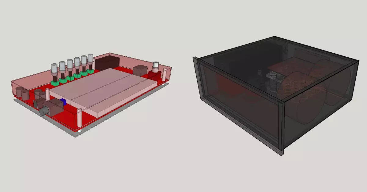
Stephen and Parker discuss how the digital and analog side of the SSPS will work and interface with each other.
USB vs Ethernet for Test Equipment?
How to make hardware work with Ethernet?
Tag Connect : Edge-Connect
Bias test connector – OTC (one time connect)
Parker is an Electrical Engineer with backgrounds in Embedded System Design and Digital Signal Processing. He got his start in 2005 by hacking Nintendo consoles into portable gaming units. The following year he designed and produced an Atari 2600 video mod to allow the Atari to display a crisp, RF fuzz free picture on newer TVs. Over a thousand Atari video mods where produced by Parker from 2006 to 2011 and the mod is still made by other enthusiasts in the Atari community.
In 2006, Parker enrolled at The University of Texas at Austin as a Petroleum Engineer. After realizing electronics was his passion he switched majors in 2007 to Electrical and Computer Engineering. Following his previous background in making the Atari 2600 video mod, Parker decided to take more board layout classes and circuit design classes. Other areas of study include robotics, microcontroller theory and design, FPGA development with VHDL and Verilog, and image and signal processing with DSPs. In 2010, Parker won a Ti sponsored Launchpad programming and design contest that was held by the IEEE CS chapter at the University. Parker graduated with a BS in Electrical and Computer Engineering in the Spring of 2012.
In the Summer of 2012, Parker was hired on as an Electrical Engineer at Dynamic Perception to design and prototype new electronic products. Here, Parker learned about full product development cycles and honed his board layout skills. Seeing the difficulties in managing operations and FCC/CE compliance testing, Parker thought there had to be a better way for small electronic companies to get their product out in customer's hands.
Parker also runs the blog, longhornengineer.com, where he posts his personal projects, technical guides, and appnotes about board layout design and components.
Stephen Kraig began his electronics career by building musical oriented circuits in 2003. Stephen is an avid guitar player and, in his down time, manufactures audio electronics including guitar amplifiers, pedals, and pro audio gear. Stephen graduated with a BS in Electrical Engineering from Texas A&M University.
Special thanks to whixr over at Tymkrs for the intro and outro!
Hello, and welcome to the macro engineering podcast. We are your hosts, Parker, Dolman.
And Steven Craig.
This is episode 294. So, if you are a listener, a longtime listener to the podcast, come check out our Twitch livestream. We are live streaming right now actually, we actually had like, we could have recorded an entire podcast before this episode even started. We we just chatted with everyone in chat for like an hour.
We have a ton of fun before the recording. So if you Yeah, if you're interested, join us live on Twitch twitch.tv/macro Fab Tuesdays at 6pm. Central.
Yeah, and I think we do need to put a like survey out the figure out when ideal times would be because Tuesday at six o'clock is kind of a weird time. But that's the time that we record the podcast normally. But honestly, we could probably move that round to whenever and whatever.
Yeah, we just want to hang out and have fun. So if there's a time that's better for people, then you know, we'll make it work.
Yeah. Expect a survey soon and a Slack channel near you. Okay, so this week, I've been working on kind of a new project, but an old project the same time. So we were doing a lot of hooking up like automating test equipment, like digital multimeters, using Python, over a USB connection and Skippy SCPI. And I was actually kind of running, I was running into some problems early on this is like months ago. And basically with issues with USB connectivity, right, where like a device would drop out. And then I had to write code to basically go find that comport again and reconnect if it got disconnected. And actually, that works quite well, by sort of looking at like, how often that happens in my test equipment. And it can make up like 15% of your cycle time of like, a device dropping out and then having to reconnect it. It doesn't happen like in a row whatever. But it ends up being quite a substantial section of your of your cycle times or could be so I started thinking of altered how else do I talk to these devices, and it be more stable maybe. Most test equipment I found also are allowed to you can have ethernet, or LAN I guess, local area networks. So I started testing that stuff out. So I hooked up some my meters scopes and stuff to a an Ethernet switch, and then hooked that up to my laptop and then kind of made my own. I had to like learn basic networking because I've never done anything patched like DHCP which is your dynamically allocating IPs. I didn't want to do that I wanted to set IPS I had to set a gateway or fun stuff. And I got managed to get working in it. Surprisingly, was ends up being faster. And I haven't had a device drop out yet. I think what what it comes down to is USB stack software that's like in scopes and that kind of stuff is generally garbage and is not really good at handling being disconnected and reconnected like having a hiccup in the communication and also on the Windows side where how it handles comm ports where if a comport disconnects or has a problem, Windows will try to reestablish it and then assign it the same comport and so that the program doesn't know anything bad happened, right? It tries to like smooth over the cracks of spackle whereas Linux on the other hand will just let it drop and then reconnect as a new comport and so Linux you have to like scan for a new port. Whereas windows it's generally the same port which in some cases is easier but it you in Linux you know something bad happened because your old comport is not there anymore. It's just shut down and you can reconnect a new one. Whereas Windows stuff tends to work fine until it just straight up doesn't work like a device will like hard lock because of that underlying driver connectivity thing that Windows is probably a specific name that what it does in Windows but I don't know it. So Ethernet, the great also the good thing about Ethernet It comes with free isolation. Most of the time on USB, the shield on the USB on the test equipment is also attached to the shield of the chassis of your test equipment, which is also attached to like on a scope, it's attached to the outside of that BNC connector as well. So the BNC connector shielding is connected to the chassis of their scope, it was also connected to the shielded USB. And so when you plug in your laptop, you are now like creating this entire chain of of shielding that if you wouldn't, depending on what you hook up to can either cause catastrophe and ground loops. Had a lot of fun exploding little scopes and stuff trying to figure that stuff out. And so yeah, oh, and Ethernet, you don't need software drivers. Like for your laptop, or your computer. Like you don't have to install drivers because it's just like, it's just an IP address that you're hitting now, right? Instead of actually having a handle a USB stack on the Windows side, or whatever Comm port it could be or something like that. So far, it's been pretty good. I just got it working. Oh, yes. Casey eight in Twitch chat makes a good point here. Make sure you don't accidentally use shielded Ethernet cabling, because then you get rid of the isolation, because now you still have the same problem as shielded cabling. And the thing great thing about Ethernet is it's kind of its has a really good reduction in noise already gets low voltage signal differential, its twisted pairs. So most of you don't get away with long distance on it long distance. And you don't really need a shielded cable like you would with with USB. I've been pretty happy with it so far, I have to do more testing. And I actually do want to like, implement it into a tester and actually figure out if it's actually more stable. But so far, I've been finding that is is faster and better.
Well, yeah. And when you say isolation, Ethernet by design is galvanically isolated, right? It has transformers in the connector. Yes,
yes. Yeah, it's by design isolated already with us v is not. And so you have to buy like, you know, a $10 chip that does it for you, or like a $40 dongle that goes in series in your series of USB cable.
I spoke with a gentleman at QFC. They make power monitors and stuff monitors as in mica, audio, Speaker monitors, and they have a series of monitors that all audios run over Ethernet. So it's basically like you can install permanent speakers in your restaurant or your office or whatever. And you just run power and Ethernet to it. And it's your 100% done, which is really cool. I love that.
Yeah, it would be even more interesting if they could if there was like a Power over Ethernet test equipments, because then you wouldn't have to run like 120 volts out to all your devices in your test rig. That might be something interesting to look at. Whenever we get around to designing that DMM that we were talking about. And actually making that only Ethernet. And so us we're talking about making it USB, but it might be the way to go is make an Ethernet compatible instead. And then also make it Power over Ethernet. Because then you would only have your you basically your switch your Ethernet switch, which will be replaced the hub, USB hub in your in your test rack could be a power Ethernet one as well. So you would only have one power source input. And then you know, it's just less wires easier to maintain by your operators and that kind of stuff.
About to see it's also easier you can be anywhere in your building and paying your equipment right. You don't have to be within six feet of it.
Yeah, technically you could be anywhere in the world to Well, you're right if you expose your test rig to a if you punch
a hole in your router.
So expanding on that, because I was trying that out today this morning. During some like meetings I'm like I don't really pay too much attention is meaning I'm going to write some Python.
So rewrite all the code that you already have.
That's the great thing you don't have to because I was writing on top of the Skippy pi visa Skippy Library. All you have to do is instead of setting up a USB device, when you're setting up your car communications, all you have to do is set up it, you have to set the point to an IP address instead, instead of saying comport one, that's the digital multimeter. You go, No, that's IP 190 2.168 dot 2.1.
And only let Windows handle everything else from there. And you
love the Windows networking stack, which is phenomenal compared to the USB stack. Because it also also handles you know, drop packets correctly and all that stuff.
That's, it's,
it's fundamentally a bunch better system. I guess the only downside is, it's also downside with USB as well, though, is it could be there could be a lag, or it's it's a, what's right word for it. Now non deterministic and timing. So if you need to send like a sync pulse or whatever, what first of all, you can't do that over USB either. But you definitely can't do that over Ethernet. It's by design, because it's designed to be an asynchronous communication protocol, TC P IP. Which is why on the back your meters and stuff like that you have a sync pulse like input that you can put in. It happens when it happens. Happens when it happens. generally happens pretty quickly though, especially if there's no other stuff on the network. So once I got that working, I got all my, my multimeters and my scopes and my power supplies all talking over Skippy with Ethernet through a local hub. or I shouldn't say hub local switch a hub is a different thing. Is that hubs different? And I was like okay, that's all my devices. But what about my custom hardware? And it's because it's running on a there's basically no doing Omega just plugged in onto that board. And I'm like, Okay, well, there's ethernet shield for Arduino. How good are they? So I got one right here. And I hooked it up. And I actually in like 30 minutes, I was able to get Skippy talking over a local LAN through that ethernet port. And it works.
Did you just pull up whatever their example code is, and then just port it over?
Yeah, I took I took their example code. And then I took my Skippy code. And I just went zippered them together, zipper them all together, and then hit compile, and it worked. And I'm like, Ah, it works. Awesome. Nice. So the hardware, or at least the pictures I have now. I'm not going to rerun boards for him, of course, but I will get mode I'll get 90% of the communication over Ethernet now. So I'm converting a lot of the fixtures over to Ethernet now just for stability reasons. I'm pretty happy with it. We'll see, I'm hoping next week, like I have like, it is better or it is the same. It can't be worse. I guess technically could be worse, but I don't I don't think my initial tests are showing that. It's way more stable. Because I haven't had any disconnects. It's like, actually I haven't like, it's still at HQ, like pinging the rack. And the rack is still like working correctly. Whereas USB would have to like had reset by like three or four times by now.
And you had to write just a bunch of if reset do this kind of code, right on the
USB side. Yeah. But on the IP side, like it hasn't been hit those reset routines yet.
Just let it sit there and ping for like a full week. Yeah. Well, I'm
gonna take it down tomorrow morning and like actually get it to start doing tests. Because right now it's just like talking to the modules. And making sure hey, are you awake? Are you awake? Are you awake? That's what it's doing right now.
I mean, that's good enough, right? If you prove that then then that's fine.
But tomorrow, I want to like set up to actually do testing and actually run through all the tests and make sure because there's more stuff that happens like running 300 watts of power through cables and that kind of stuff. And that tester I see. It's like is like the worst case scenario for a tester.
But But like you said with with twisted pair Ethernet and an isolation, it's sort of the better option in that scenario. It
is the way it should be better should be better. Yeah. So we'll see
because you're hoping on common mode, noise. Rejection so quickly.
So I was thinking about your you got your comment down here, the bias test connector? Yeah. I don't know if we I think you should talk about that before I jump into my next thing. Yeah, yeah, let me jump on that. I think they're kind of paired they'll pair together really well,
this is just this is a relatively quick one. But but I've been developing my bias test system, which that's been going fairly well, I'm still writing code for it, I actually am running into a goofy thing where, you know, previously, I had it, running channels with one channel and pinging it and getting data off of one channel. And I expanded that to multiple channels. And then I was like, Okay, great. So this is all functioning well, so I'm going to expand it to all channels. And I do that. And the only thing that's changed is now I'm now going all channels as opposed to a few. That's the only thing I changed in my code. And it'll do like four or five reads. And then the Arduino just craps. And we'll stop communicating. So I've got some kind of goofy timing USB bug to work out with this, which is annoying. But regardless, I'm working sort of on the other end of the connector, or the bias test system, I developed a test connector. We've talked about this a little bit in the past, but I've been I've been looking for some kind of thing I can use in production, that allows me to connect to my main PCB without populating a connector on my main PCB. Because I'm making an OTC I call it a one time connect thing such that in production at the very end of production, I plug in a test header thing that connects to my board gathers data, the user will unplug it, and then hopefully in the life of the device, it never gets used again. So I don't want to spend money and populate a connector for a one time test. So I ended up developing a little test connector that uses pogo pins on the actual connector side of it. And then on the main PCB, there's just a bunch of exposed pads. And what's nice about this is all of the pogo pins, they have a, they have a decent diameter, I don't remember what it's like 70,000, it's actually fairly fat. And they have about two millimeters of travel. So the thing is, I can have up to 500 volts on these pogo pins, so I have to space them out properly. But whenever I'm not using the connector, there's still voltage on the pads that these pogo pins connect to. But because the pogo pins have a domed head on them, I can actually make the test pads a lot smaller than the pads that the the pogo pins themselves solder into. Which is great, because in the lifetime of the device, it would be terrible if the device shorted due to a one time connector thing. So it's kind of nice, because the so the target pads, I was able to shrink them considerably. So I have a huge amount of distance in between each pad, my creepage. And clearance distance is well over what I need, which is spot on what I was trying to design. The next hurdle with this connector was to make it such that it's really easy to plug in. And it holds in place. Like I don't want hands inside of my devices, because there's some safety precautions about that and I want I want the user to plug it in, press a button on the computer and then the computer does everything else. So sort of like a tag connect connector. But I at first I was like, do I design my own tag Connect? Do I get Parker to 3d print be crap and send it up here and I was I was going that route and I was like there's gotta be a solution. So I ended up finding on PIM pen, pen engineering, their their website, they have these, these hardware studs that are called the port numbers SMT SSS dash, four millimeter dash six e t, which is basically it's a, it's a PCB connector that is a steel stud that is cut with, it's basically split such that it has a spring action to it. So so with you sorted them into my little connector board and just put holes on the board that is supposed to mate to and this should snap into place and hold the all the pogo pins, right where they need to be, and be relatively easy to pull out once once you're done. So I have a handful of those. What's funny is in the component shortage right now, if you try to go find these, they're not available anywhere in the world right now. It's not well, this particular pepsin actually, this entire family of pens Dutch can't find them anywhere. And mousers like I'm gonna get them December 12 or whatever. And I'm like, I don't want to wait that long. So I found a soy pen hit me up the other day and I was like samples. And so they were like Sure why not. So they found a place that they usually sell them by reel in 1000s. But they were willing to do some cut tape and send me some samples, which is great. Because right now for development, I only need three of these for my little connector thing. So the hope is that it's, it's really easy to snap in and snap out. And since these studs are made of steel that like basically just cut steel, if they ever, if they ever weaken a little bit, you can just put a screwdriver in it and pry them open just a little bit more and give them some more grip strength. So but in reality, good.
No, keep it I'm sorry, I didn't know I was gonna cut you off.
Oh, no. Well, I mean, I was just saying, basically, they're not going to be used very much. It's not like I'm using them on 10,000 devices. It's more like it would be it would be great to see them use on 100. So I think I think they will certainly survive that.
I've used the family before, and I have the exact opposite problem is that they have ridiculous hold strength. And they are in pot. It's like, they're, they're great for installing terrible for removing.
Sure. So I actually I designed a board the other day that it's on its way now. But I put five copies of this footprint with varying hole sizes on them. So the datasheet recommends some hole. And yeah, it is supposed to be it's not like a one time thing it is supposed to be removable. But once once you click it in, it's supposed to hold pretty damn well. Yeah, I'm
hoping to use it.
Oh, to press it in?
Yeah, actually, I made a tool that it's just a whole like a to basically that presses over it. It traces the, so you can pull it off.
Yeah, I'm thinking that if I just oversize the hole, I can kind of fine tune its grip strength, because it just has I have 16 pogo pins, it just has to be good enough to hold back the spring force of 16 pogo pins, which are not much right. Yeah,
the only. only other thing I can think of with it is is those peptides been really strong. And you basically snapping your connector in and never never comes out ever again. But it was oh, I can't remember what else I was gonna say about those. Those headsets,
here's the here's the nice thing, the location on my main board that this is going to click into has four BV hardware studs that that mount this Board to the chassis. So I mean right in that area. So I'm not expecting much PCB flex whatsoever, even if this is a pretty stiff connection. So I'm not I'm not terribly worried about that. Also, all of my pads are enormous. And the traces are too, so I'm not worried about too much flex damage. We'll see I've got a test board coming on its way, it'll be funny, because I'm going to have an actual physical amp with wires going to a test board, this test board will have terminal strips that go off to one of my footprints that go off to one of this new test connected, that go off to a ribbon cable that go off to the bias tests. Like I'm trying to test all the way down the system without actually building the entire system.
Oh, so what I was saying is, the other thing is because you're trying different hole sizes. Yeah. It's gonna be interesting. Depending on the PCB board fab, it's going to depend on what drill they actually use for that hole, which is funny to think about people. But depending on the FAB, they can have either they usually either have a metric drill machine, or they have an imperial drill machine. And it doesn't matter what country it is. It's it depends on the fab because it's depending on the fab whether or not they have a they might have both, but most time they have one or the other. Or they might just mill the circle. Well, they might depending if it's big enough. Yeah, they might mill mill the circle. And so but the thing is, if you designed a Imperial hole, and you shipped it to a fad that you're going to use a metric hole, then they actually will just pick a metric hole that's just close to the size. Again, their tolerance.
I was sad. Yeah, they state their tolerance on it. They'll pick one that overlaps between a drill.
Yes, yeah. So they'll pick something that's in that tolerance range. Which might be
bad for this. It might be on the edge of your tolerance might Yeah,
or yeah might be on the edge of one of those tolerances, which makes these pen studs either bite too hard or bite not enough. That's the only other thing I can think of that might be bad. Now, if you standardize on one board manufacturer, then you probably won't have to worry about it.
I ordered these boards from the same one that I would order production from right now, or at least I'm planning to, and I don't think that this is. So the I've got three of these PEM studs they hold like crazy. And like I said, they're only holding back against three or 16. Small springs, I think I could get away with with a reduced holds or a hole size that's larger that would reduce the holding force and make it easier for inserts and, and taking it out.
Yeah. So in Twitch chat, DJ mentions, so tag connect question mark. The reason why I'll answer this the reason at least I think the reason why the reason why not tag Connect is because of the high voltage
100%. Yeah, Tech Connect is like 30 volts maximum, I don't remember what it is. But it's I need Okay, so I need 500 volts minimum. During test, this, this connector could be subjected to 500 volts. So
what's your what's your creepage keep, keep talking because I'm going to find my Tech Connect, and I have my my multiple calipers and I'm going to measure what the creepage on this will be
my creepage right now, or my clearance distance from pad edge to pad edge is over 75 Tao. I think it's actually a little bit bigger than that at something, though. The biggest problem with this is is even if Tech Connect could handle 500 volts, the pads on the main PCB that I'm trying to read, those need to be able to withstand the voltage when the amp is actually running, which do too to the fact that my amps use an output transformer, the voltage can swing well over the steady state quiescent voltage. So say I have an amp that's running at 500 volts. in steady state, that might be fine for for the test connector. But when you're playing at full bore, that 500 could swing up to 750 800 volts. So I need to be able to have enough clearance for that on my PCB and just there's guaranteed that Tech Connect isn't gonna work. So the whole goal here is to make a tag connect like system that can handle 500 volts. So you need
a bigger pitch, because the swipe measured is on the tap Connect. So tap Connect is a connector that's got basically pogo pins in it. You press it into the board and it flexes and hits all the contacts. And so a pogo pin is a shaft of brass, basically, that goes into a sleeve of brass that's got a pin spring in it, and so that when you move the shaft in and out, the spring compresses and allows some compliance in the connection. Yeah. So your your closest connection, which would be your creepage. Honor, well, it could be either in this case is both Yeah, yeah. Is basically between the sleeves, right of the pogo pins, because obviously the largest diameter part of the pogo pin, and those measure 225 mils,
which, you know, you could get away with, I don't know what 25 could do, you're not gonna get 500 on 25 mil, so it's 25 I have point 125, I have eighth of an inch clearance between, well, that's my pitch is eighth of an inch on my pins. And and that's exactly so what you're talking about the sleeve of the pogo pins, that that matters for my connector, but the target pads on the main PCB are smaller than the sleeves of those. So I have higher clearance for for when the test connector is off, and the amperage is running. But when I'm actually doing the test, my clearance goes down because the connectors in there, but I'm not actually sending signal through my amp when I'm doing the test. I don't want to actually do that. So it sits at whatever that quiescent voltage, and I've designed all my amps to be 500 or lower. So I can handle the slightly lower clearance when the connector is plugged in. But when it's not plugged in, I have even higher clearance so it kind of all works out.
So doing a quick just throw numbers at an online calculator for IPC two to one be a tag Kinect if we're just going off the sleeve of the pogo pin that's in the connector itself because it could be even closer inside of the of the molded enclosure but I don't know. And I bet you're tacking it probably might have a specification and we just we're just ignoring whatever it says on the website, but the sleeves hang up. You could do 100 volts because it's 100 volts needs 24 mils of clearance at Okay,
so maybe maybe you could do 48 feel comfortable?
Yeah. If you wanted to have a 2x margin. Yeah, yeah.
But I mean, in all reality, we're doing like five volt max on tech. And yeah,
most time you're doing low voltage, yeah, you're on tight connect.
And most of those ribbon cables are rated at 300 volts. So you're pretty much your limiting factor is the pitch of the actual pogos.
Yes. I'm trying to see if they actually have a specification on the voltage. And I don't think so because I think a lot of times they sell Miss applications. They don't sell like this as a cable. They say this plugs into X programmer, which is probably a
smart inherits. It's, it's numbers. Yes.
It inherits the environment.
We don't know what here's what it is, if you're asking these questions, tech connects not right for you.
Could be because like I built I built a lot of adapter boards for TAC necks that looked like this. Yeah, that allowed me to use like, one style, tactics, techniques, approaches, right. They are expensive, like $60. They are expensive. But they are so nice biome, what I do is I buy one style. And then I build adapter boards that allow me to plug multiple different programmers into them. And also, the great thing about doing that is you can abuse them by using pins that the SE programmer only has is only using two pins. Like the six pins, I'll technics Well, you have four other pins to do other things with like apply power and ground through it. So you can do usually you can power your board. So because a lot of programmers don't, don't power up, they'll have power over the programmer. Or they do it's very limited and you can't like power an entire list for example, Pinball board, but I can power an entire pinball board over tap Connect with my adapter board, which is really nice when you are doing testing and validation. Because then I only have to do is plug that one thing in and it gets power and all that good stuff. So I so it's interesting that they don't actually specify that they might add look really quickly on the website. I didn't see it. They do. We'll update it next week and saying that they they have that specification. But I wouldn't be surprised if it's somewhere if we went digging. Yeah, but I definitely abuse it because I do put power. Now the most power of airpro technic is 12 volts. And actually it's the first time I've ever measured that clearance on it too. So I would not I would probably be okay up to like 75 volts. But again, the pump the problem with that though, is you have exposed pins that's at whatever voltage it is to well okay in your in your fingers tend to be down by the pogo pins as you're like jabbing it into the board. So high voltage is probably not a good thing.
No, it's not good. Well, okay. And here's the thing, what you're also assuming there is that the contacts on the PCB are exactly the same diameter as the pins and you're hitting a spot central in the center. Yeah, so your your clearance is going to be less on the PCB footprint than it will be on there. So it's probably not even 100 volts from the footprint side. Yeah,
I'm just looking from the Yeah, from other than a pogo pin spacing.
So we got a product that we're getting a little spiffy with at work. I designed it now, such that the Tech Connect is multi use. So you can plug it into a programmer and and program your processor and then you unplug it from the programmer and you plug it into a separate header. And it can control the processor on the board rearranges the programming pins and it can control a power supply. And you can plug the power supply into itself and it can calibrate itself through a Technic cable. Oh, it's getting fancy now? Well, I'm trying to I'm taking a process that it's been around for a long time and it works fine. But it's a process that is incredibly manual where somebody is looking at a thing where the clicking buttons going through and monitoring system. And I was like this can all be done in the processor. And it can be done way better and less subjective. So let's have the processor do it. And let's use this tech connector while we're at it. So works out really well actually.
So we've been talking a lot about Tech Connect Tech Connect if you want to sponsor a podcast. Yeah, yeah, for sure. Drop us a line at podcast@macro.com because that'd be a lot of fun. because I do like your products a lot. And we are going to talk about new product they I don't know if it's new new, but it's new new to me. It's new to me. I saw it last week for the first time. Yeah, so tacking next got a new connector called Edge connect. And it's exactly what sounds like it's a, it's a spring loaded leaf spring connectors. It's not pogo pins, but they're like, spring loaded, spring loaded. But they're like a leaf. Yeah. And it slides onto the edge of your board through cancelations on the edge of your board. And I was looking at them. That's a really good idea. Because I actually have run into problems with some products I've designed that I cannot fit a normal tack connect connector, mainly for once you start shrinking stuff down, and you start doing double sided load and like your density goes up so high, you just you still can't find a spot to fit that connector. Yeah. And how many times I've we've like chopped off like the, the locating pins off attack connect to so like, because sometimes you have a part on the other side of the Kinect. And so you don't have like the you can't you don't have a free bore. For the locating pins.
It makes me cry every time I've had to do it.
Yeah. So yeah, you have to cut off a pin off. You're like $60.
Yeah, so this has like a little locating. So you basically the footprint is a little hole in the board that is close to the edge, and then a row of cancellations. Yes. And so you kind of slide and an alignment pin into that one hole that you drill. And all of these leaf contacts spring over on to the cancellations.
Now, we were talking about this new edge connects in chat as a chat, it's Slack. So macro.com/slack, we're talking about this. And there's like a while back, we actually talked about to the SOC, like clips, where you they make clips that you can attach to like IC components. And there are some people who repurpose those four actually like clipping onto the edge of a board, like cancellations or pads. So you can do like kind of like attack connect. And I actually experimented with those a lot. And I felt that they're, they're okay for programming, if you only needed like attached for a little bit. But the moment you try to do anything like you're trying to do debugging, or JTAG, or anything like that, where your connection needs to last longer than about 10 seconds, they just flop off or like, disconnect because there's no locating pin, because like it just it's just grabbing on by tension. So these solve that problem by having that locating pin. So basically, once you put that connector on, it's not going to come off unless you want to come off.
You know, okay, so there's, there's three things real quick about this, that I think might be some downsides to it. First of all, it's even more expensive. So it is more like $84 for one of these connectors, which, you know, not a big deal if you need to buy one or two for your engineering team. But if you were needing to buy a whole slew of these for production, that could add up pretty quick. Yeah, I would agree. So that's, that's a little bit weird. One thing, that little alignment pin, he's pretty close to the edge of the board, your board house might not be super happy about drilling that close to the edge of the board, because there might be blowout, or you could damage the board. If you're just a little, you know, if you push a little too hard, a little vigorous, yeah, some figure in there. And then the other the other downside that just comes to mind is that this sort of, it doesn't require it, but it tends to make your layouts you'll want to put your processor near the edge of a board and in mind that your processor wouldn't make sense to be next to the edge of the board. And then you have to weigh do I send my programming signals halfway across the board to get to an edge. And so there's a little downside to that.
The thing about I used to be like that too, like I'm like, Oh, those are like like high priority signals and blah blah, not nothing is the used typically once or twice in the lifetime of your product. Right. And and the great thing about those, those wires, as long as they're not being used for anything else, like some people like well, we'll use all the pins and reap Programming pins, but most people in products don't. You don't have to worry about them in like, emissions and stuff. Because when your product is running, you're not sending anything over those pins. So you can just have really long traces and doesn't matter.
Well, it's just it's just annoying because you're just eating up board space for a one time thing.
That's the thing with any kind of programming connector. The only way to get around that is to pre program your microcontroller, which has its own slew of problems. Yeah, because I'd say you've got to say I'm going to lock in my firmware like like six months before you even gonna start like assembling boards Yeah, maybe not like you might be able to get away with three months before but you got plus months.
I think we got Robo Parker how's that sound for everyone and twitches at Robo Parker Parker for our route
this technical malfunction break is brought to you by stupidity we I
don't remember where we left off at Has anyone in chat? No. So because editing this together is gonna be really hard. Josh ours sound engineer just put in like when like the connection drops, just put some like music or something in and then like intermission will start now. Yeah, yeah, the Monty Python and the Monty Python. That's it. Let's go through. That's always my favorite. And you can keep this stuff into the castle. Ah, my favorite skit of that is the one where I can't remember the Knights name. But when he's running at the castle,
is that Lancelot?
I don't know if it's my Asana. But it's a castle. And like, it's the two guards like eating the apple. And it always like, it's like the music resets when they like look when the camera pans down and looks at him running. And just keeps resetting that one shot for like, five minutes. And then he shows up at the gate and like stabs the guards. So I think that's my favorite gag in that whole movie. Yeah, it's
Lancelot. That's, that's, yeah, that's
such an Aussie that entire movie is gold. So
I mean, the ending is kind of like, he just like they're like, Oh,
we've done like an hour and a half. We need to finish. Oh, yeah. It's like they ran out of ideas. And we're like, well, let's just end just like this podcast, right?
Is that your segue to end the podcast?
Yes, I'm actually that would have been a really good segue to end the podcast. But I wanted to throw this out to chat and our slack. I say chat, I mean, Twitch chat. And, and our Slack channel is. So next week, I think we're going to do another idea fab podcast. I think that's what's I think we still have to confirm it. But I think that's what's happening next week. If slack, or Twitch chat, or Twitter or whatever, our community comes up with some ideas that we can pitch us like community ideas. Steve and I are going to come up with ideas. And an idea fab, they're going to come up with ideas as well. And so if we had community ideas to, that'd be great.
I just checked. So it's looking like two weeks from today. Oh, it's Tuesday, September 28. But that's great. That gives that gives us two to two weeks to come up with some community ideas. So we've had the idea of podcast the idea cast, guys, come on what this is, this will be the third time the third time yeah, this will be their third time. So I don't remember the numbers off the top of my head. But go look back through our episodes. We're this this next one on September 28. That's tentative right now. But I think we were close to confirming that. This will be similar to that. And we've had so much fun every time we've done these episodes. So basically, we just come up with ideas and then pitch them to the other guys on the podcast. So yeah, I would love to see some community ideas. That would be awesome. It was, uh, episode number 77,
which is just called the idea fat podcast. And that was back when we were recording with Josh down in Castle Bravo. Yeah, at the basement of the old post office downtown in Houston. Before Oh, man, that must have been like, only like a month or six weeks before Hurricane Harvey. He wasn't in there super long. No, no, it wasn't long and it was very Shortly after that podcast that we had to stop recording it. We actually stopped recording with Josh for a while because Josh couldn't do any recording or anything like that either. Yeah. And then Episode 223, which was May last year, which was like, two or three months into COVID COVID locked down. Yeah. And that was called episode 223. The inverse of the inverted success funnel. I can't remember what the inverted successful was, I have
to go back and listen to those just so I can remember what it's like. Yeah, I liked that idea. Let's let's, at the end of the podcast after we've all done our things, let's pick some of the ones from slack and then call out community. Yeah, projects or whatever you guys come up with. Yeah.
This is actually this is probably one of my favorite like, collaboration podcast episodes. There's just so much fun.
Well, okay, so we'll call this out. We'll we'll call this out again next week on the on the episode. But I guess if you're in our Slack channel, that's one of the best places to put the ideas and just make it super clear like say like, Hey, this is an idea for the idea fad cast, and we'll log that somewhere and put it somewhere.
So that was the BackRub engineering podcast, where your host Parker Dolman
and Steven Craig. Later Everyone, take it easy.
Stephen and Parker discuss how the digital and analog side of the SSPS will work and interface with each other.