Circuit Break Podcast #243
Schematics and Connectors, Name a More Iconic Duo…
Related Topics
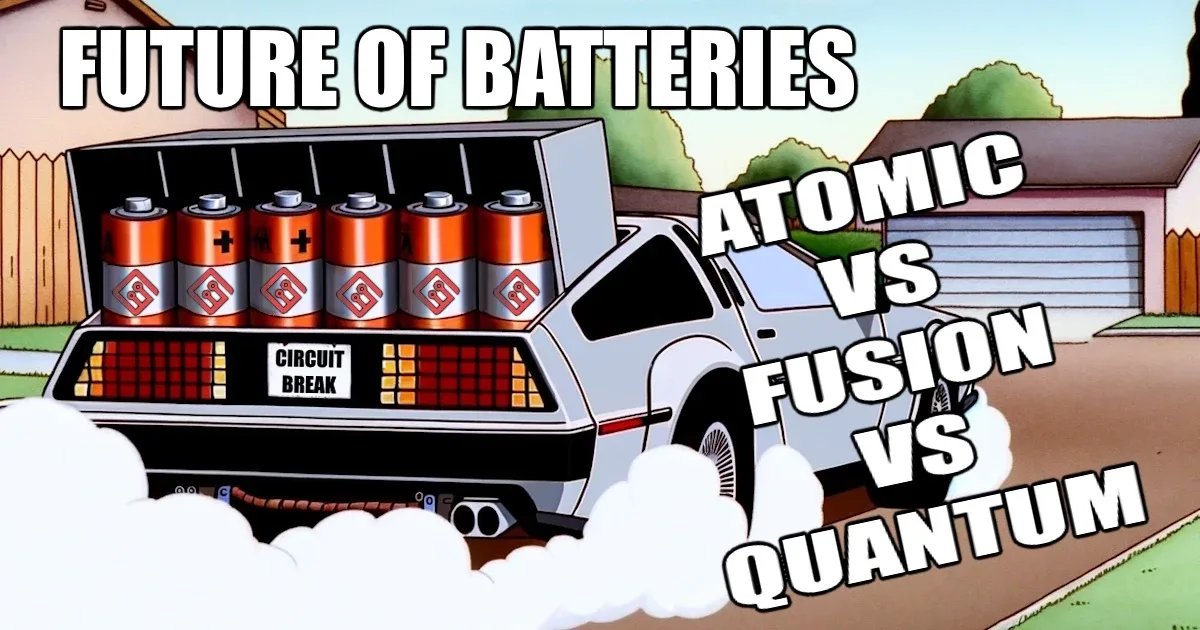
Entangled Steam
Parker and Stephen dive into the world of batteries, sparked by the BetaVolt BV100's claim of a 50-year lifespan.
Laser Cutting Tolerancing
They may be known for being electrical engineers but on this episode, Parker and Stephen dig into the more mechanical aspects of their current projects
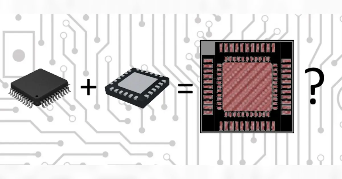
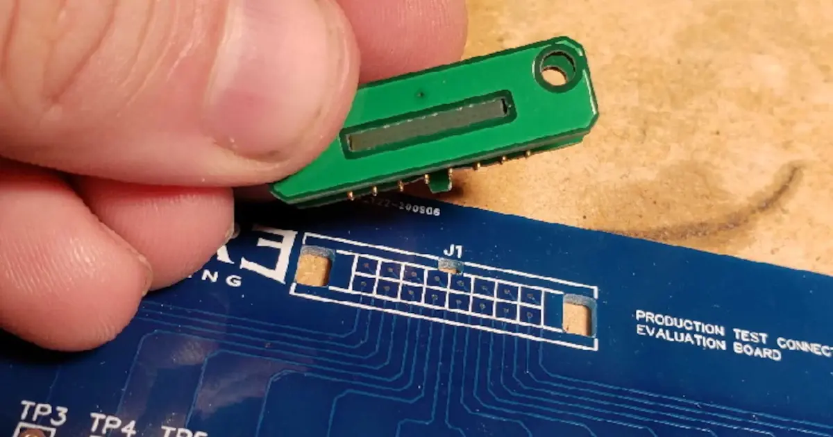
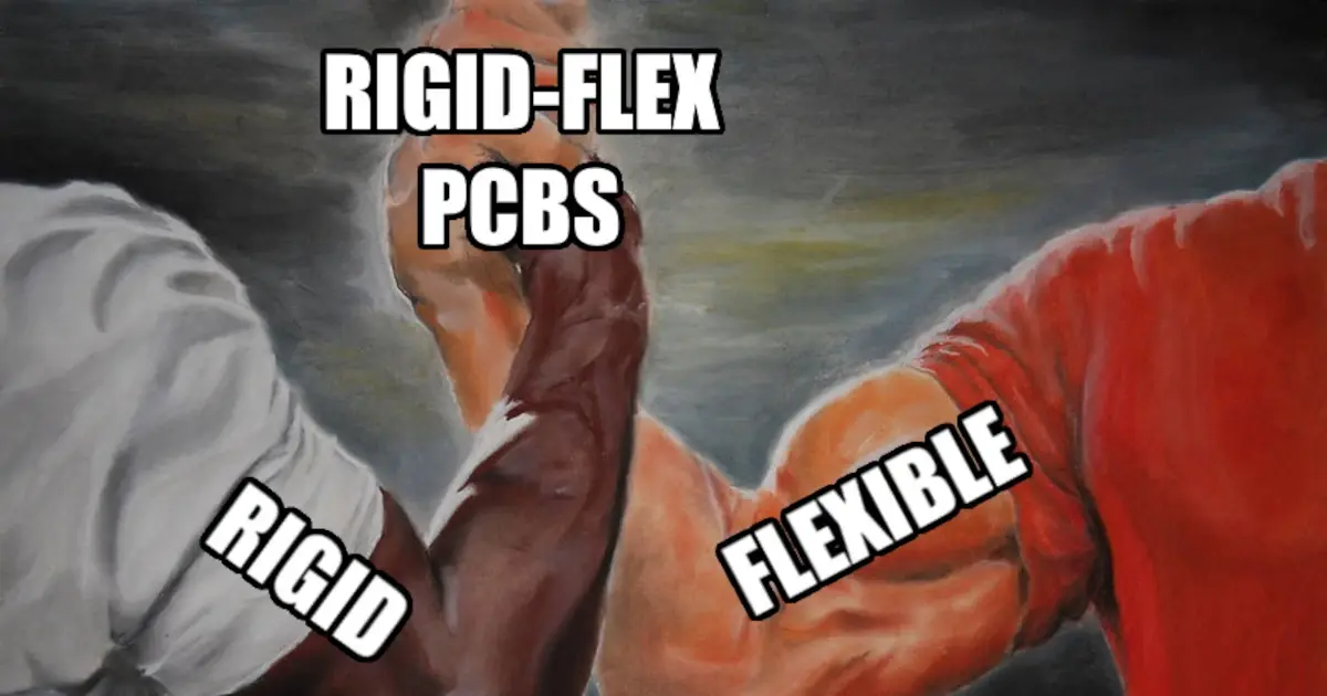
Flex PCB Primers
Stephen gives the MEP an introduction on Flex and Rigid-Flex PCB assemblies while Parker looks at an automotive Analog Devices application note.
Other Resources
Circuit Break Podcast
Webinars
Videos
Tour MacroFab's ITAR-Compliant Facility
September 23, 2020, Episode #243
Parker
- Battery Charger debacle update
- Two batteries recovered, One failed
- Amazon Sidewalk draws electronics from among TI, Silicon Labs and Semtech
- Amazon Sidewalk, a new shared wireless network for IoT consumer device
- DXF to Board outlines?
- Eagles DXF importer doesn’t work all too well
- Suggestions?
- AutoDesk Fusion seems to import just fine
Stephen
- Connectors on schematics
- Rfdave on slack channel asked a question about this
- Am I the only person who hates a schematic consisting of 1 connector, 2 IC’s, 4 bypass caps with all of the interconnects being done with net names, and no interconnecting wires?
- Currently working on a design that has multiple boards with cable interconnects
- How do you like to show this?
- Reference Designator?
- Rfdave on slack channel asked a question about this
- Potentiometer board – one board to rule them all
- Using slots to make panel mount “solder lug” potentiometers into pcb mount
- Not a lot of values in each taper is available in a through hole version
- This means a lot less wiring is required.
- EDA schematic and grounding
- Using slots to make panel mount “solder lug” potentiometers into pcb mount


About the Hosts

Parker Dillmann
Parker is an Electrical Engineer with backgrounds in Embedded System Design and Digital Signal Processing. He got his start in 2005 by hacking Nintendo consoles into portable gaming units. The following year he designed and produced an Atari 2600 video mod to allow the Atari to display a crisp, RF fuzz free picture on newer TVs. Over a thousand Atari video mods where produced by Parker from 2006 to 2011 and the mod is still made by other enthusiasts in the Atari community.
In 2006, Parker enrolled at The University of Texas at Austin as a Petroleum Engineer. After realizing electronics was his passion he switched majors in 2007 to Electrical and Computer Engineering. Following his previous background in making the Atari 2600 video mod, Parker decided to take more board layout classes and circuit design classes. Other areas of study include robotics, microcontroller theory and design, FPGA development with VHDL and Verilog, and image and signal processing with DSPs. In 2010, Parker won a Ti sponsored Launchpad programming and design contest that was held by the IEEE CS chapter at the University. Parker graduated with a BS in Electrical and Computer Engineering in the Spring of 2012.
In the Summer of 2012, Parker was hired on as an Electrical Engineer at Dynamic Perception to design and prototype new electronic products. Here, Parker learned about full product development cycles and honed his board layout skills. Seeing the difficulties in managing operations and FCC/CE compliance testing, Parker thought there had to be a better way for small electronic companies to get their product out in customer's hands.
Parker also runs the blog, longhornengineer.com, where he posts his personal projects, technical guides, and appnotes about board layout design and components.

Stephen Kraig
Stephen Kraig is a component engineer working in the aerospace industry. He has applied his electrical engineering knowledge in a variety of contexts previously, including oil and gas, contract manufacturing, audio electronic repair, and synthesizer design. A graduate of Texas A&M, Stephen has lived his adult life in the Houston, TX, and Denver, CO, areas.
Stephen has never said no to a project. From building guitar amps (starting when he was 17) to designing and building his own CNC table to fine-tuning the mineral composition of the water he uses to brew beer, he thrives on testing, experimentation, and problem-solving. Tune into the podcast to learn more about the wacky stuff Stephen gets up to.
Special thanks to whixr over at Tymkrs for the intro and outro!
Related Podcasts
Entangled Steam
Parker and Stephen dive into the world of batteries, sparked by the BetaVolt BV100's claim of a 50-year lifespan.
A Couple Months Ago…
Meta data for electronic components? Stephen talks about categorizing components to make it easier to get to that part that you really need.
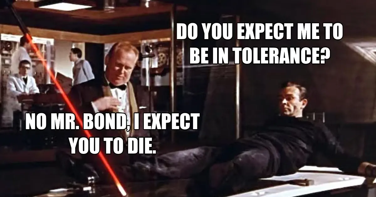
Laser Cutting Tolerancing
They may be known for being electrical engineers but on this episode, Parker and Stephen dig into the more mechanical aspects of their current projects
Critical Path Components
Designing a new product but worried about all these component shortages and increasing lead times? This week, Parker discusses designing around this.
The Heartbeat of Cats and LEDs
How do you know if an electrical component is inexpensive? When it says "Cost Effective" as a main bullet point on the datasheet!
Flex PCB Primers
Stephen gives the MEP an introduction on Flex and Rigid-Flex PCB assemblies while Parker looks at an automotive Analog Devices application note.
About MacroFab
MacroFab offers comprehensive manufacturing solutions, from your smallest prototyping orders to your largest production needs. Our factory network locations are strategically located across North America, ensuring that we have the flexibility to provide capacity when and where you need it most.
Experience the future of EMS manufacturing with our state-of-the-art technology platform and cutting-edge digital supply chain solutions. At MacroFab, we ensure that your electronics are produced faster, more efficiently, and with fewer logistic problems than ever before.
Take advantage of AI-enabled sourcing opportunities and employ expert teams who are connected through a user-friendly technology platform. Discover how streamlined electronics manufacturing can benefit your business by contacting us today.