Circuit Break Podcast #138
MacroFab Design Contest: Blink an LED – MEP Favorite
Related Topics
Does not respond after opening LOUD?
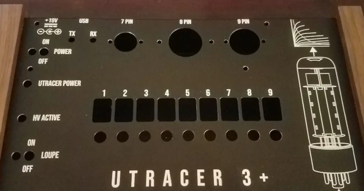
Stephen and Parker announce the MacroFab Design Contest and discuss learning about FPGAs and the uTracer.
Other Resources
Circuit Break Podcast
Webinars
Videos
Tour MacroFab's ITAR-Compliant Facility
September 19, 2018, Episode #138
We would like to thank everyone that entered into the MacroFab Design Contest: Blink an LED Sponsored by Mouser Electronics. The winner for the Pragmatic Blinky was Dillon with the Disintegrated LM3909 – 1.5V LED Flasher. The winner for the Most Complicated Blink was Paul Gallagher with The Bouncy Thief LED Blinking Machine. And The winner for the Wearable blink was Gerben with the Led eyelashes.
- MacroFab Engineering Podcast Favorite discussion
- Winner : Bobricius with the Solar-powered flashing LED heart pendant PCB coil
- Stephen
- TPS4021 4.5-V to 52-V Input Current Mode Boost Controller
- PMP8621 TI app note for doing an 18V to 300V@ 10mA supply
- Datasheet issues
- Two dimension drawings?
- The thermal pad – What do you connect it to?
- TPA3116 – 30W from an 18V supply
- TPS4021 4.5-V to 52-V Input Current Mode Boost Controller
- R.F.O.
- RE: Simulation talk from last week
- David Patterson emailed in and suggested HyperLynx Design Rule Checking (DRC)
- RE: Jeep Wagoneer Project
- Brian Gosney emailed in about his ’77 Dodge Colt Radio project
- Taking the stock AM radio, removed electronics and replaced them with Brian’s own design
- Bluetooth connectivity
- Fuel Injection: MegaSquirt?
- Brian Gosney emailed in about his ’77 Dodge Colt Radio project
- OpenMV Cam H7 – Machine Vision w/ MicroPython
- The OpenMV Cam H7 is an open-source MicroPython powered machine vision camera designed for low-power real-time applications
- More powerful than the previous version (2x)
- Removable camera modules: Global shutter and thermal sensor support
- Kwabena was on MEP EP#27: If There is a Bug, You Can Fix It
- RE: Simulation talk from last week
Visit our Slack Channel and join the conversation in between episodes and please review us, wherever you listen (PodcastAddict, iTunes). It helps this show stay visible and helps new listeners find us.

Bobricuis won the category MacroFab Podcast Favorite for the MacroFab Design Contest: Blink an LED Sponsored by Mouser.

Bobricius’ Solar-powered flashing LED heart pendant PCB coil project. Front side.

Bobricius’ Solar-powered flashing LED heart pendant PCB coil project. Back side.

Stephen’s Vox and a Box schematic. Work in Progress!
About the Hosts

Parker Dillmann
Parker is an Electrical Engineer with backgrounds in Embedded System Design and Digital Signal Processing. He got his start in 2005 by hacking Nintendo consoles into portable gaming units. The following year he designed and produced an Atari 2600 video mod to allow the Atari to display a crisp, RF fuzz free picture on newer TVs. Over a thousand Atari video mods where produced by Parker from 2006 to 2011 and the mod is still made by other enthusiasts in the Atari community.
In 2006, Parker enrolled at The University of Texas at Austin as a Petroleum Engineer. After realizing electronics was his passion he switched majors in 2007 to Electrical and Computer Engineering. Following his previous background in making the Atari 2600 video mod, Parker decided to take more board layout classes and circuit design classes. Other areas of study include robotics, microcontroller theory and design, FPGA development with VHDL and Verilog, and image and signal processing with DSPs. In 2010, Parker won a Ti sponsored Launchpad programming and design contest that was held by the IEEE CS chapter at the University. Parker graduated with a BS in Electrical and Computer Engineering in the Spring of 2012.
In the Summer of 2012, Parker was hired on as an Electrical Engineer at Dynamic Perception to design and prototype new electronic products. Here, Parker learned about full product development cycles and honed his board layout skills. Seeing the difficulties in managing operations and FCC/CE compliance testing, Parker thought there had to be a better way for small electronic companies to get their product out in customer's hands.
Parker also runs the blog, longhornengineer.com, where he posts his personal projects, technical guides, and appnotes about board layout design and components.

Stephen Kraig
Stephen Kraig is a component engineer working in the aerospace industry. He has applied his electrical engineering knowledge in a variety of contexts previously, including oil and gas, contract manufacturing, audio electronic repair, and synthesizer design. A graduate of Texas A&M, Stephen has lived his adult life in the Houston, TX, and Denver, CO, areas.
Stephen has never said no to a project. From building guitar amps (starting when he was 17) to designing and building his own CNC table to fine-tuning the mineral composition of the water he uses to brew beer, he thrives on testing, experimentation, and problem-solving. Tune into the podcast to learn more about the wacky stuff Stephen gets up to.
Special thanks to whixr over at Tymkrs for the intro and outro!
Related Podcasts
Does not respond after opening LOUD?
Stephen and Parker announce the MacroFab Design Contest and discuss learning about FPGAs and the uTracer.
About MacroFab
MacroFab offers comprehensive manufacturing solutions, from your smallest prototyping orders to your largest production needs. Our factory network locations are strategically located across North America, ensuring that we have the flexibility to provide capacity when and where you need it most.
Experience the future of EMS manufacturing with our state-of-the-art technology platform and cutting-edge digital supply chain solutions. At MacroFab, we ensure that your electronics are produced faster, more efficiently, and with fewer logistic problems than ever before.
Take advantage of AI-enabled sourcing opportunities and employ expert teams who are connected through a user-friendly technology platform. Discover how streamlined electronics manufacturing can benefit your business by contacting us today.