The history banana connectors with Stephen! Then Parker brings up Elon Musk's Neuralink Implant for happy pigs and why projects take forever.
Need to find a transformer for your product design? Stephen goes through the process of getting a custom transformer manufactured for a new product!
High voltage and low current measuring got you down? Stephen looks into how he is going to measure the specifications for his tubes.
Parker
Stephen
Parker is an Electrical Engineer with backgrounds in Embedded System Design and Digital Signal Processing. He got his start in 2005 by hacking Nintendo consoles into portable gaming units. The following year he designed and produced an Atari 2600 video mod to allow the Atari to display a crisp, RF fuzz free picture on newer TVs. Over a thousand Atari video mods where produced by Parker from 2006 to 2011 and the mod is still made by other enthusiasts in the Atari community.
In 2006, Parker enrolled at The University of Texas at Austin as a Petroleum Engineer. After realizing electronics was his passion he switched majors in 2007 to Electrical and Computer Engineering. Following his previous background in making the Atari 2600 video mod, Parker decided to take more board layout classes and circuit design classes. Other areas of study include robotics, microcontroller theory and design, FPGA development with VHDL and Verilog, and image and signal processing with DSPs. In 2010, Parker won a Ti sponsored Launchpad programming and design contest that was held by the IEEE CS chapter at the University. Parker graduated with a BS in Electrical and Computer Engineering in the Spring of 2012.
In the Summer of 2012, Parker was hired on as an Electrical Engineer at Dynamic Perception to design and prototype new electronic products. Here, Parker learned about full product development cycles and honed his board layout skills. Seeing the difficulties in managing operations and FCC/CE compliance testing, Parker thought there had to be a better way for small electronic companies to get their product out in customer's hands.
Parker also runs the blog, longhornengineer.com, where he posts his personal projects, technical guides, and appnotes about board layout design and components.
Stephen Kraig began his electronics career by building musical oriented circuits in 2003. Stephen is an avid guitar player and, in his down time, manufactures audio electronics including guitar amplifiers, pedals, and pro audio gear. Stephen graduated with a BS in Electrical Engineering from Texas A&M University.
Special thanks to whixr over at Tymkrs for the intro and outro!
Hello, and welcome to the macro fab engineering podcast. We are your host,
Stephen Craig and Parker Dolman.
This is episode 240.
So we got a new tool, I guess. Can you call this a tool?
You know, I'm going to be talking about i Well, I do because I have the show notes right in front of ya.
So you got a new automatic screen printer.
It's a machine.
When does it go from a tool to a machine? Hmm. Because a power drill? Yeah. Like the modern power just like a brushless one is got a computer in it that's figuring out how to fire the motor depending on your switch input. I mean, is that any different than a complicated words like computer learning with vision control, putting pace down and through apertures?
You know, I was at first I was gonna I was gonna say like, a tool is potentially mobile and a machine is static. But is a forklift, a machine or a tool at that point?
Yeah. Or like you can put casters on anything.
How much does How much does your new tool machine weigh?
I don't know how much that thing weighs. But I just remember the when we got the new reflow oven that Heller, it came on casters.
Yeah, I mean, we still rented a forklift for that.
Yeah, we moved that. Like we moved the box in on the forklift. And then we took it off. We picked it up off the pallet, right? And then took the pallet away. And then you wheeled around on these ginormous bike, almost like 10 inch diameter casters. And then you got in the right spot, and then you lifted it up, took the casters off and then put it on its feet. So yeah, the mobile doesn't work because technically, you could just leave it on those casters and then you have a you know what, at 180 amps that 400 Whatever volt three phase tool?
I'm sure you well is plenty fine with that. Yeah. So okay, what new tool machine did you get before we go to meta into this?
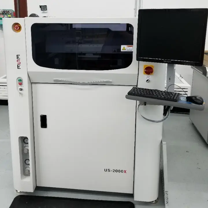
So we got an ESC U S 2,000x. Automatic screen printer. I came in this week. I don't know I don't know too much about it yet. But looking at its specifications, it looks like maybe we can potential lower or minimal pace aperture size, which would be cool. Because previously, our ML pace aperture size was dictated by our jet printer machines. So we actually, for longest time we didn't use stencils at HQ, we would, we would basically use a really fancy laser printer that would use a little piezo element and vibrate. solder paste in our parabolic arcs as it's shot around a board and deposited pastes really cool technology bomb paste balls. Yeah, exactly. Really cool technology. But it's limited on on how small of a.it can bombard the board with
well, each.is the minimum size, right? Yeah, that would be the
minimum size. And so basically, if we had to go with a dot size that was too small, you had to go stencils. And so we had a like a semi semi automatic machine to cover that bases. And then of course, like our partner factories, they'll have fully automatic machines, but we finally got a fully automatic machine now. And yeah, so I'm looking forward to see if we can drop our minimal piece size, which would be pretty nice, because that's like our biggest request for our DRC is to design real check is to like get that number lower.
Well buy a new tool machine. And there you go. Yeah. So actually, you know, I for for people who haven't manufactured a board or seen a line, why don't you describe what a automatic screen printer is? Because it's actually kind of cool. So if you think it's cool, I mean, I think all of this is cool. Yeah, that's true.
It's like making. So it's a screen printer. And so a screen, what a screen printer is just a generic screen printer is you have a a usually a piece of stainless or just some kind of material that's got openings in it. And then you whatever your screening goes over that and then you squeegee the material across and then as the squeegee goes across the screen, it presses the material into the screen and into whatever you're screening. So you can make posters, you can make T shirts. It's funny not to think about like screen printing T shirts was like, a thing my parents did when they were like kids It's and like, no one knows what the hell that is now,
well, when you screen printing, T shirts and things you usually use like a mesh fabric that has, you know, been UV cured and has the openings in it. And depending on the mesh size, it's it's actually the same process they use for applying silkscreen to your board. Whereas with a with, like a paste printer, you're actually talking about openings in a steel sheet. That paste gets pushed through. And you know, it's funny if you've never actually seen it, or didn't even know that, like, if you're playing around in your EDA software. And you see like the software complain because it needs to have its apertures to find those apertures are literally the openings in that steel plate that you're messing with.
Yeah, messing with. Yeah. And it's, it's surprisingly, a very low tech way to build very high tech things. Oh, yeah. It's screen printing has been around for ages. And it's just a really good way of uniformly applying a viscous or non viscous I guess, material. What would solder paste be? Because it's not really? It's like non new Tomac? Actually, almost. It's paste. Yes. Paste. It's almost like peanut butter. Yeah, peanut butter is good. Good way to explain it. Yeah.
It depends on, you know, actually super fine,
chunky peanut butter.
Yeah, like if the, if the chunks were, I don't know, a mil across or something?
Yeah, what's the what's type four, type five paste. So yeah, there's also different types of paste, giving, what the size of the solder balls that are in the paste is and also the tolerance between the ball sizes. So like a type five is like a super fine, but also very concise. Paste was a type three is like, who really cares? What the ball sizes? Right?
Yeah, yeah, you know, some of the best part about all of this is that if you're going to get your product manufactured, everything we're talking about is not something you necessarily need to care about. Most of the time, your, your CFC M handles, it handles all of this, the only thing that you really need to worry about is defining the page to apertures on such that when that central is cut, it's actually has the holes where they need to be and you know, they sort of the there's some rule of thumbs when it comes to, you know, paste, reduction and things. So you typically make the opening smaller than the actual pad, because you don't always need as much paste as would fully cover the pad because it will spread out. So that's the one thing that you as the designer have some control over.
And the thing about that is to always talk to your CM. Because I'm Acrab, we, we prefer one to one, when we get it. Some manufacturers are fine for a reduction or whatever. But yeah, we like to have one to one. But like, for me, when I'm designing, I'll leave most of those pads one to one. And then if it's a large thermal pad, like for underneath apart, I will go ahead and window that is usually what I will do. Because I know the bankruptcy and processes everything's one to one. And they'll see that window and understand it's a window and
yeah, you know, I wonder now. So Mac Feds process has always been one to one not always, but it was one to one because you guys had the the micronic or the my 200 right or the 500 by 500. And you guys could selectively adjust apertures if you needed to. It's not even an aperture at that point. Because you could just shrink ghupat If you needed to. But now that you're getting into the stencil game, you may not go one to one all the time.
Yeah, that's on our our manufacturing team that decide.
Right, right. Yeah, actually the way that setup if the customer provides one to one for you, and then you get to adjust the, the apertures for everything. That works too. But in general, you know, in so many ways, like we talked about this all the time. It's like, if you're not sure, just ask your CSM, and they probably have at least some guidelines to point you towards. Exactly, yeah.
Yeah, so we're still sticking with the one one man because we've been using stencils for a long time now. It's just that we have a newer machine that we can talk about. Know a new tool. Hey, yeah, that's right. There's gotta be some there's probably some IPC number that says this is a tool and this is a machine.
Oh, sure. Yeah. And if you violate that they find you
Yeah, only if you pay for their PDF.
That is a final most so you know, one thing that's that's Cool, we actually started getting into this about a year and a half ago at WMD. And it's been turning out really well for us step two pencils. So stencils that have two different thicknesses, so you can apply thicker levels of paste at in certain areas. And so we we have migrated to using a significant amount of surface mount headers now, and we actually use some fine pitch stuff. So, you know, 1.27 millimeter is some of our stuff uses two by 20 connectors that are all surfaces. That
is because you're stacking boards and your product. Yeah, we most
of our products are two boards stack up, and we use surface mount female and male in between the two boards. And we can use step stencils to selectively apply more paste to the legs of those versus say, an Oh, two component that's nearby that doesn't need nearly as much and I think just these little drop, right, right. And we also use a handful of pretty hefty mechanical components that get abuse, like mechanical tax switches, and things like that, and we put more paste on those. So you know, it's funny, the difference in price, though, really starts to stack up fast, because a just a Joe Schmo stencil is, I don't know, 15 to $25, somewhere in that range, and a step stencils $400 You have to commit to it. And, but but in what we've done, a lot of times is is do prototypes without a step stencil, because we can fix anything if we need to. And then when we go to production, drop the money and get the good one. Yeah,
the that's actually the very, the best, not the very best benefit, but one of the best benefits of the the micronic, paste jetters the printers, that just is you can say, I want to put like a ton of paste on this one pad. And it can just bombard that one pad with tons of paste. Just carpet bomb it. Yeah. But that's actually the best thing about it is is you can, it's actually would be a good idea is if you're iterating on on pace apertures, basically, you could dial that in with a pace jet machine, and then go ahead and buy a stencil, it wouldn't be faster. It's like the difference between injection molding and 3d printing, you can iterate on a 3d print to a certain point, get your final design and then take that and get get a mold for it.
I think that's a great if you guys are not already doing that, like it's ramping up to production for for clients, like if they do like say a 10 piece run on on the line. And and you kind of like iron out all the bugs, and then you buy the expensive stencil one time and you've got it all fixed.
Got it all fixed. Yep, yeah. That's all I have for that that stencil printer. I'm looking forward to actually learning it though.
They're fun. The machines that operate them are surprisingly complex, even though they just kind of like, I don't know, wipe a squeegee across a stencil, you know, exactly, because they have a lot of optical stuff going the big thing
with stenciling that you really have to take care of, I guess is one is your pace life and your shelf life with the pace because if it's in there too long, it gets kind of crunchy is a good way to put it. It's all it turns instead of being like a smooth paste, it gets ya chunky and and it doesn't want to smooth out anymore. And then the second thing is your stencil can get dirty. And that's especially if you start running a lot of the same panels over and over and over again and haven't cleaned your stencil in a while is the apertures will start to pick up some of that crunchiness and then and some of that because basically because you know the pace is just flux with a binder and then a bunch of solder balls right. And so eventually that pace starts to dry out and it starts attaching and cleaning to inside the apertures and then you don't get good releases it so you can either oh we're going to clean the stencil after X panels and then we guarantee it but a lot of times you still have a good life out of your your stencil basically still then so what you can do is you can do optical inspection on some of the smaller features on your boards. And so then you can basically check that and say okay, now that's starting to degrade let's go clean the stencil now and so then you get rid of environmental factors and you know if you're changing paste brand that has one has a longer shelf life one doesn't stuff like that.
You know, I actually have a an interesting story about paced life because I ran into it. Monday of last week where I so I got a whole bin of units that were you know failing. And they, you know, the testing department was like, I tested this and I got 0% yield, everything's not working. And they sent it to me and I looked at under microscope. And I see, I see some interesting features on on our boards that normally I
don't see. It's like when you go to the doctor, and you get your test results back and they say interesting, anything really bad.
So it looked like Okay, so if you look in the IPC, 610 Dash whatever revision they're on now, there is a page that describes a type of solder that's called disturbed solder. And it looks weak, and it looks wavy, and kind of cracked. And I was noticing that across a handful of boards, and and usually what disturbs solder, you have to have physical movement, you have to disturb the solder joints while it's cooling, and you get a weird like fractures and as things kind of solidify. So the thing that was interesting though, is I zoomed in a little bit further, and I noticed that the solder joints I noticed that the solder joints were actually basically perfect. But there was a layer of flux on top of that, as the flux cooled, the flux cracked and it didn't completely boil off. And it was interesting paste, and the flux didn't burn properly as it went through our reflow oven. So we pitched that that paste, did a whole brand new bottle, a paste, and the very next run was perfect. And actually what was funny was the reason why those units were failing is because we had a small bug in firmware. And it had nothing to do with soldering, but like people were like, the solder is bad on this.
No, no, it's interesting is we're actually we are probably gonna start running into that now at the FAB, because our pace jet uses a different kind of paste, then our screen printer does just from the nature of how the pace jet works, it needs a specific blend of flux and unicorn blood in the machine, right? 11 are events, that unicorn blood, that unicorn blood makes it crossed over the solder joints. And whereas when you do a normal pace, usually you don't have any of that it usually boils off at the end of your reflow Yeah, but on our pace jet machine, we that how it's it's just sticks around, and there's nothing that you can do brand new pace does it and it's just that's
hard to get why so so the the thing is, like, if you if you have the if you have the oven set just right, like if all of the stars align, and everything solders well, that that most of that burns off, and what remains is clear. If you get stuff that looks like earwax, and it's cracked all over the place, just pitch the paste and just, it's it's a $60 tub of paste, like, Don't worry,
check your profile, but no is that that pace leaves a clear, shell eggshell over the pace of the over the solder and there's nothing you can do about it. That's just the nature of whatever. Unicorn that's, that's when you reflow unicorn blood. That's what turns into.
And that's why you buy super sharp multimeter probes so you can crack through that to measure things.
Yes. We just put a link to those multimeter probes we keep recommend.
Yeah, for like seven bucks. I bought a pair the other week. They're great. Yeah, they were great.
Yeah, until they roll over. But they're sharp. There's nothing you can do about it.
Or until you slip and you short, some stuff and some smoke comes out because that totally didn't happen to me the other week.
I was actually about say stab your thumb, which I've done before.
But they're great. I like them.
Yeah, they're very good. That's that's, that's the best thing is because we had a Oh, bald engineer James Lewis on and we were talking about lab equipment. I think it was last episode we had him on. And we're talking about multimeters. And I'm like $20, multimeter and $10 probes.
Actually, our buddy texted Barker, and I the other day was like, I want to buy a multimeter. And he's all like I'm ready to spend 150 bucks or like
I'm like on a fluke, and I'm like, Nah, buy the $20 one and get a $10 of probes and you'll be just fine.
And well, and that's not to say that, like I wouldn't want to Fluke myself in my lab, but I just know when I need accuracy and when I don't. And 90% of the time I don't need accuracy 90% of the time I just need a continuity test. Well, no, it's just
it's just what he needs. I would say this is if your life depended on a multimeter you get a initial standard multimeter that's going to stand up in court if it is and habit NIST calibrated. Yes. That it's is is if a lawyer is going to go after you. You want a a miscalibrated multimeter Yeah,
but if you'd like this guy and working on model trains, a $20 multimeters fine.
Now how big of a train has to get before it's not a model train, it's a regular train,
we, we don't need to go down that path. We've already been on like 40 tangents this
so before we jump into your next topic, we're gonna keep this tangent train rolling.
Let's go is.
So we talked a little bit about this in our Slack channel. And I want to gauge people's reactions if we started to do a twitch livestream of the podcasts, so it would be like Steve and I are talking and I think we're gonna try to do it, where it's just Stephen and I are just talking to each other. And then at the end, we look at the chats and see what the questions are.
And we see everyone been like, you're wrong about everything ever. Yeah. It's like
being fact checked during the whole thing. But I, I want to try that way, mainly from I think if it was Stephen and I, and chats at the same time, it might be a little weird. Yeah, we might try a podcast doing that just to see how it goes. But given the fact that this is an audio podcast, people not being able to see the chat would be weird. Whereas if we did like a chat q&a At the end, where like, people could submit questions, and we could read the question, and then answer it, that might work better. So let us know in Slack, or on Twitter, or an email, podcasts america.com. If what you think
so I guess we'll have like a, I mean, we already do have a particular recording time, but we'll just release that and people can get on live and yes, questions? If if we have anyone who is
anyone that wants to pop on at six o'clock central time on a Tuesday?
Hey, we've we've actually done a handful of live things. And there have been people and it's been fun. Yeah, in fact, the the coding thing that we did together was we wrote some firmware together to drive. Some of the seven segment displays on my you tracer. And we had we had a handful of proto debounce functions what we did well, yeah, yeah, cuz I had I had a lot of the skeleton behind there. But yeah, the, it was the debounce function and the interrupt code that went in there. Yeah, that was fun.
Oh, the micro trace. That was the project I was thinking about. Someone was asking on Slack. What about a wooden project enclosure? Yeah, that was Derek. Yeah. And I'm like, oh, seven. Totally use that same enclosure, that exact numbers. Yeah. Yeah. I can't remember what it was my micro Tracer was the project. Yeah. So Steven, what do you been up to?
The last week I was talking about? Well, the last couple of weeks, I've been talking about high voltage, low current measurements. And I've finally just said, like, Okay, I'm figuring this out. Everyone's been super like helpful on the Slack channel in terms of giving me suggestions on things. And I kind of deviated a little bit and change my mind on some things, because I added a little bit of a stipulation to the kind of underlying design criteria. And one of that was, I didn't want to handle this like a traditional ammeter. In other words, I didn't want to break a line and stick something in there, I wanted something where I could plug in a connector and get the data and then unplug the connector. And I didn't have to break a line or do anything other than plug in a connector. So that kind of shoehorns me into well, let me actually add one more little caveat to that. I didn't want to add any components to the board that I'm measuring either. So okay, yeah, I just want something that can sniff the board and give me data and then like, it's like it was never there
poofy popcorn.
So, so that Okay, so what that basically does is it means that I am stuck with measuring low voltages where low voltages exist. And then the old school method of read a voltage on one side of resistor, read a voltage on the other side of the resistor. And you know, the resistance, you can calculate to whatever whatever the tolerance is, the current that flows through it, so that's what I'm basically going with now, I discussed as I'm holding these up, Parker's seen this, but these high voltage resistive dividers that are like they can handle something like 1200 volts and they have pretty high precision laser trim resistors inside the one of these devices that I'm going with is the cat och 1776 dash c 6810. Yes,
the freedom resistor.
Right. I think you've made that joke. I made the same joke. So, so yeah, because
the point it's point 1% resistor, it's point 1%
global tolerance but all the resistors inside have a point. Oh 5% resistor to resist.
Yeah, resistor matching ratio point oh, 5%.
Right. So it's pretty dang good. Basically, it's a, it's
a voltage divider, that's all it is. PPM drift to,
it's meant for doing exactly what I'm doing effectively take a high voltage make it a low voltage, generally accurately. So this guy is 10 megohm. Total, it's five resistors. So it's got a nine Meg 900k 90k 9k, and a 1k, to equal up to 10 meg total. And so with four different tabs, you can get 1/10, voltage 1/100, one 1001 10,000. So I'm going to pull off of the 1/100 Tap such that a zero to 500 volt input to the resistive divider gives me a zero to five volt output. And then I can interface that to an ADC and start getting some values. And I can put two of these one on either side of a screen resistor in my amps, read the voltage across it, and then I know what value that resistor is. So I can type it into whatever program I'm going to develop and just say, what's the current through it? And that'll I don't see any reasons why that won't work out, other than the fact that these resistors are like 16 bucks a piece, which kind of sucks. But you know, I, I'm not making a ton of these,
well, what's your slow current? Are you making sure that on your on your resistor divider is gonna be high enough impedance to make sure you're not gonna be getting any parasitic draw?
Yeah, so the the most of the time, the resistors, that I'm going to be reading across our 1k maximum. And so if we're talking about a resistive divider of 1k, and 10, mega ohm, I don't think I'm going to be getting any kind of massive gain errors out of that. The interesting thing is there, I did run into a different gain error. And that's kind of what I wanted to talk about with this, because I ended up doing a bunch of research on what EDC I wanted to grab for this. And originally, I wanted to get a 16 bit add, because that gave plenty of resolution. And the problem was I just, if you've ever searched for ADCs, you can spend a week and a half searching for like the perfect one. And the problem is, like I just kept searching, it's just like, hi everyone. Like, I didn't get that warm, fuzzy feeling that you get when you find the component that you love, you know, and eventually, I stumbled on to just randomly a another part that would be MCP 3551 Dash II slash s n, which is not a 16 bit add. I think this is actually a microchip part. Let me look it up real quick.
It's MCP so yeah, yeah, yeah,
it's a it's a microchip part. It's a 22 bit A to D. That has plenty wonder.
I wonder if MCP actually stands for microchip part.
I wouldn't be surprised like so many of their parts start with MCP.
But regardless, this thing is a 22 bit A to D, which is way more accuracy than I need. It's not particularly fast. But all the rest of the characteristics about it like its gain error and things like that. I'm not, I'm not worried about that. It's plenty good enough.
Yeah, it's also like you're measuring the current, how quickly is the current going to be changing that you want to measure
everything here is DC. So this thing can read 13 and a half times a second, which is ridiculously slow. But yeah, even if it read two times a second, I'd be fine. You know, it doesn't I don't need an update refresh speed that's through the roof, I'll probably try to get it around 10 times a second. And that's way more than enough. Also, I'm going to be measuring like 12 of these. So I like all at I don't need a ton of measuring speed. So they're their SPI chips. So super easy to talk to. The one thing though, that made me raise an eyebrow is they have 2.4 mega ohm input impedance, which generally that's moderately high. It's not like super high. But I got me thinking if I plug this thing into a tap on a 10 mega ohm, voltage divider, I'm going to be screwing with my ratios like crazy because 2.4 Meg is plenty enough to start messing with the ratios on that. So I actually decided to calculate it out and see like how bad would it be if I just raw plugged this thing into one of these voltage divider? Resistors I got and ended up coming up with, if it's connected to the 1/100, tap on this resistor, I get a gain. Well, the ideal gain is point 01. But the gain of the everything becomes 0.0096. So it is reducing it as you would expect, because now you're putting impedance in parallel with some other resistors in the voltage divider with effectively the bottom resistor in the voltage divider, you now have something in parallel. So in fact, the the resistance of the bottom leg of the voltage divider would be 100k. So I've got 100k in parallel with 2.4 Meg, you do parallel resistance and you get not 100k, you get something less, right? Yes. And so I want it to be a gain of 0.01. But I'm getting I would get 0.0096. And at full scale, if I put full five volts into that, I would get 4.8 volts. So that's enough of an error that I'm not okay with that. That would also that 2.4 megohm is not a controlled spec on the device. So if I had 10 of these in there, they could be all over the place. Right? That's gonna give you a tolerance for that. I don't think so. It's just that I think that's the typical value. I don't remember what it said. But I wouldn't ever trust that to be like, guaranteed.
Yeah, you can't hard code in 0.0096,
right? Because I thought about that I was like, well, if it's guaranteed, but I know it's not guaranteed. And so, yeah, you would just be building in error by doing this. So I came up with a solution, which is not particularly flashy, but I decided to add a buffer in there. But the whole reason why I'm talking about this, is because I found a pretty cool little buffer that I wanted to talk about.
And you know, it's not often that you hear that guy, cool little buffer.
Well, with this thing, I think this is this thing is pretty legit. And it's not cheap. It's like six bucks and singles. And it doesn't get more expensive than your ADC. Yeah, these ABCs are a little less than $4 and singles. And the buffers more buffered the buffers more, but this is a quad buffer, so I only need two of them. Two of them. Or no, I actually need three, three.
Yeah, you're going to 10. Right.
I think I have I have 10 to 12 things to measure. I haven't decided how much more and I might add some expansion into it. So I don't know.
Go to 16.
Just add more of them. Yeah, yeah. Why not go to 20? Come on, feature creep it that I think I think that's, by the way, that's our roles in this podcast is to like poke each other to feature creep more.
Well, I don't know if you remember that one project. I had the octo prover, which was an eight channel so you can have a dual October.
Oh, that's right. Yeah. Yeah, you have to prove it was cool. You should finish that one day. I have no idea where it's at. It was super cool. And like the case look cool. So for
those that don't know, that was an eight channel thermocouple reader for doing basically measurements. Reading. Well, it's for like 3d printers. So like, you could tape them all down to your bed and get like a heat profile of your bed. That was kind of the idea. Yeah, yeah. You're asked to do that project after the cat feeder. Okay. October, not to mention on
this episode, actually, if you finished the October, whatever, I will buy one for sure. Like that's super useful.
Yeah. Okay. Okay. Yeah. i Oh, by all parts and quantity of two. Now.
I'm pretty sure you don't want one of the things I'm making here. It would not be useful to you in any way. So So okay, so check this out. This, this buffer chip that I found is the ad 8244 br MZ. It's basically just a quad buffer. So it's like the most boring chip ever. You put something in and the exact same thing comes out the outside, right, that's the whole point of a buffer. And that's what you want to happen. Yes. So the cool
thing is just just a piece of wire inside of the chip,
guaranteed unity gain today. So the typical offset voltage from this thing is only 100 micro volts, so it's pretty low offset, and then across temperature, I think you can get to like 600 micro volts or something like that, which is kind of nice, because that's so low, but with my 22 bit add, I should be able to read that. But I can just have a like an offset calibration in my device. Basically, without having any current flow through it. I can just go to my software that I write for this and just say like, zero out and whatever, so I can zero that out easily. It's just nice that the typical offset voltage is already really, really low. but it's not going to throw things off. Cool thing is that has a gain error of 0.03% on plus minus 15 volt rails, which I'm going to run it somewhere close to that. Here's the thing that's really nice about it has a 10 Tera ohm and four pico farad input resistance and input capacitance. So he's its input bias current is two pico amps. So it basically is invisible to it's like the dividers.
Yeah, it's like the, like, if you had a trace, your trace is going to have more parasitic stuff on it, then this device does
so so you know what's funny, there's a whole section of the datasheet that talks about that specifically. In fact, this this, they they put a very specific pin out of the of the buffers inside the chip, such that you can make guard traces around Oh, yeah, I'm looking at that right now. Yeah, you can make guard traces, because fr four, if you lay it out incorrectly, will have higher leakage current than the device itself. So in order to get like a perfect buffer, you have to put a lot of effort into your layout to make things just right. But okay, so check this out, I recalculated everything, if I use this buffer in there, instead of the 2.4 mega ohm input impedance of the A to D, if I replace that with 10, Tera ohms, which is 10 times 10 to the 12th. Power, resistance, what does my gain go to? So previously, my gain error was 0.0096, or not the error that was the gain. Now, if I if if everything is ideal in the game, it would now be 0.009999999901. So that's eight nines behind there. So effectively, I just wrote in the show notes close enough, you know,
yeah, that's, that's, that's, that's a point. 001.
Right. Actually, you know, what's funny, I'll probably get more error from the gain of the unity in the buffer than I will now from loading down my voltage divider. Yeah, you're actually probably right. But I'm willing to accept that. That's, that's fine. And
that's also you already, you already accepted. That was, you were going to get
that for sure. I was I was gonna get that. So
I love I love this challenge. Because just to do something simple like reading current, you have to really dig into a lot of other things, because it just keeps adding problems. Every solution that myself or everyone in the in the Slack channel comes up with there's been some really creative stuff, but like every single time, it's like, ah, but that adds so much work and so much extra crap.
Well, like the best ones were like just using those those Lego chips, right? But the best, the only problem with those is like your resolution was like three or four bits. Yeah, it
was, it wouldn't have been good. So like I talked about on last podcast, so I'd have to add a bunch of gain, that's not ideal. And then at the same time, I put another stipulation that makes those Lego chips not really work too well, I don't want to break the trace. I don't want to insert this thing into the circuit, I want to be able to just sniff things, which basically means I got to detect voltage. So So yeah, there we go. Got that all taken care of. I ended up this last weekend throwing together a whole schematic with well, it's almost unknown. But I'm gonna just go cheapo, easy Arduino root, and throw a 328 P, and an ft 230. X on a board and just have it talked to all of these, all of these ad DS on there, and all at once. And then I'm my my plan right now is to actually write a Processing sketch on my computer that can talk down to the A to D and then I can just, I basically make a super custom data acquisition system for guitar amps.
Cool. Yeah, I'm looking forward to it. Yeah,
uh, hopefully I've got some stuff on order for my like, super unique connector system. So everything's on order. Stephen has not told me what this thing is yet. I want to I want to show it off once I have it. And once I have it working,
so you have to have a logo for this board. It's like am I like a? It's like an eight armed octopus playing guitars. I liked or an eight guitar neck. Guitar, eight neck guitar.
Oh, you know what, you just kind of screwed everything up now because like now I need a nice logo. And I just realized, like, I need to put it in another one of those wooden boxes that Derrick was going to use, like I need to buy another one of those.
You gotta do that now. Yeah. So you If you weren't What did you say earlier? Your Your
job is to feature creep my projects and that's my job for you.
So before we wrap up this this episode, let us know in the in Slack or on Twitter, whatever if you want to start doing Twitch live streams, let us know. And yeah, I think we're wrapping this thing up.
Cool. So that was the macro fab engineering podcast. We were your host Stephen Gray,
and Parker Dolman Take it easy. Later.
Need to find a transformer for your product design? Stephen goes through the process of getting a custom transformer manufactured for a new product!
The history banana connectors with Stephen! Then Parker brings up Elon Musk's Neuralink Implant for happy pigs and why projects take forever.
High voltage and low current measuring got you down? Stephen looks into how he is going to measure the specifications for his tubes.