The Venti-Q gets nears completion, USB Type-C example circuit completed, and EE interview topics.
Parker wraps up his Wagon Chime Module and looks at USB Power Switches and Stephen covers his EQ build.
Parker talks about his Embedded System Design process and Stephen explains his 20 band EQ design!
Congratulations to our Slack member Mobius Striptease! Mobius’ pulse generator won first place at their Senior Design Expo!
Article written about MacroFab: Houston electronics manufacturing company gears up for growth. Talks about the growth of MacroFab over the past 2 years.
Visit our Public Slack Channel and join the conversation in between episodes!
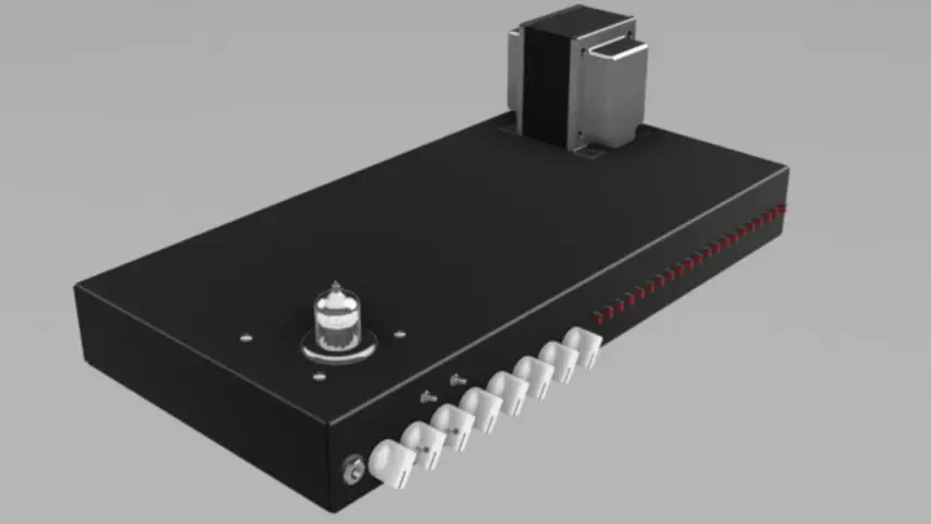
Stephen’s Amplifier rendered in Autodesk Fusion.
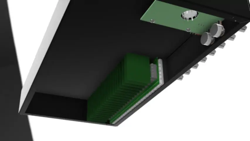
Underside of the amplifier. Not all the components are modeled yet.
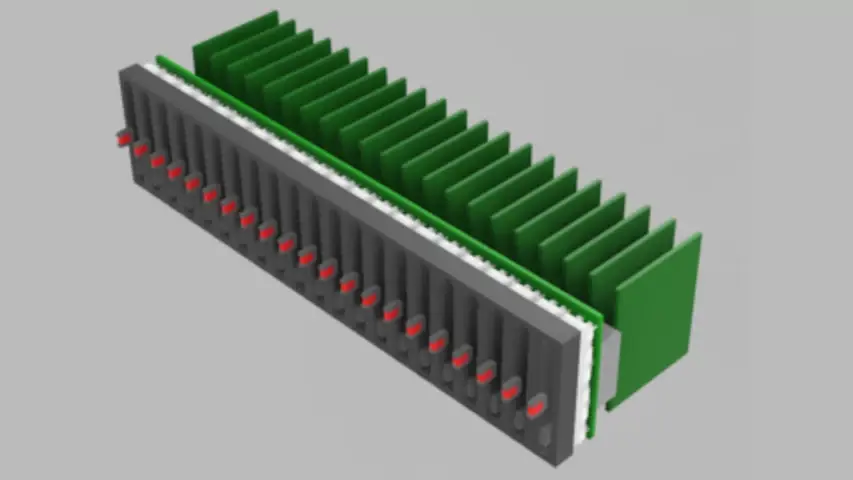
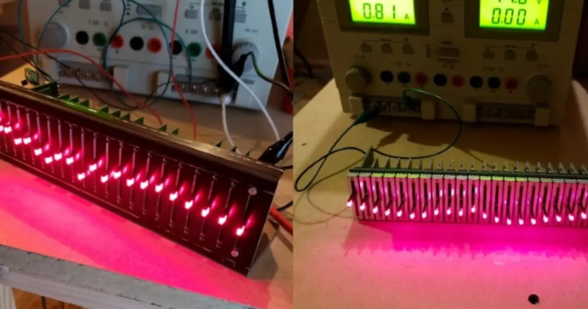
The current iteration of the 20 Band EQ module for the Amplifier.
Close up of the PCI-Express connectors and slide pots.
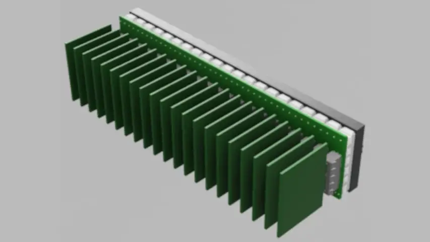
Almost looks like a heatsink!
Parker is an Electrical Engineer with backgrounds in Embedded System Design and Digital Signal Processing. He got his start in 2005 by hacking Nintendo consoles into portable gaming units. The following year he designed and produced an Atari 2600 video mod to allow the Atari to display a crisp, RF fuzz free picture on newer TVs. Over a thousand Atari video mods where produced by Parker from 2006 to 2011 and the mod is still made by other enthusiasts in the Atari community.
In 2006, Parker enrolled at The University of Texas at Austin as a Petroleum Engineer. After realizing electronics was his passion he switched majors in 2007 to Electrical and Computer Engineering. Following his previous background in making the Atari 2600 video mod, Parker decided to take more board layout classes and circuit design classes. Other areas of study include robotics, microcontroller theory and design, FPGA development with VHDL and Verilog, and image and signal processing with DSPs. In 2010, Parker won a Ti sponsored Launchpad programming and design contest that was held by the IEEE CS chapter at the University. Parker graduated with a BS in Electrical and Computer Engineering in the Spring of 2012.
In the Summer of 2012, Parker was hired on as an Electrical Engineer at Dynamic Perception to design and prototype new electronic products. Here, Parker learned about full product development cycles and honed his board layout skills. Seeing the difficulties in managing operations and FCC/CE compliance testing, Parker thought there had to be a better way for small electronic companies to get their product out in customer's hands.
Parker also runs the blog, longhornengineer.com, where he posts his personal projects, technical guides, and appnotes about board layout design and components.
Stephen Kraig began his electronics career by building musical oriented circuits in 2003. Stephen is an avid guitar player and, in his down time, manufactures audio electronics including guitar amplifiers, pedals, and pro audio gear. Stephen graduated with a BS in Electrical Engineering from Texas A&M University.
Special thanks to whixr over at Tymkrs for the intro and outro!
Hello, and welcome to the macro FEHB engineering podcast. We are your host, Stephen Gregg
and Parker Dolman.
This is episode 150.
How, how'd this happen?
Somebody's letting us do this. And I don't know why.
So, just like we've gotten to 150 episodes, so congratulations to the Mac five engineering podcast. But also congratulations to one of our Slack members. Mobius strip tees, his pulse generator won first place in their Senior Design Expo. Ooh, congratulations. So I first I thought it was really awesome that they won their senior design contest or expo or whatever project thing at their college. But the fact that his screen names also Mobius strip tease, I'm like, I can see that on the pie. This guy's a winner. So Mobius, if you could share, I don't think you've ever shared your project on the slack. So go ahead and share it with us if you can.
Yeah, and maybe we'll showcase it on an episode. Yeah.
And then also macro fab news, there was an article written about macro fab the innovation map, which is a website that does, like startups, news articles on startups and stuff. They had an article about us and the article is titled, Houston electronics manufacturing company gears up for growth. And they basically talk about how Mac fab has grown over the last two years. So go check that out. That's all I'm gonna say about that. It's pretty good article. So it's like tooting your own horn, so to speak. Just a little bit, a little bit. Okay, so on to the podcast, I guess. So I've been working on that Raspberry Pi, that Raspberry Pi three compute module board. I got the audio part routed. That's the PCM 5122. That was really easy. I basically just like lifted off my previous board design and just plopped it on to my computer module board. And that's that's a TI guy. Right? Yeah, that's a TI part. And it's a I two s i square C controlled. IC for doing? You know, it's an audio DAC.
Did you follow their recommended layout in the datasheet? Or did you kind of cook up your own?
Um, I don't think it has a recommended layout. Oh, it just has guidelines. Yeah. Just has guidance. I followed all the guidelines. This is that DAC that you tested? Oh, so long ago.
This the one that had the you did the different
capacitors on right. Yeah, the different loadouts. And we ended up finding that the cheap one sounded better.
Yeah. And in a blind test. Yeah, that was pretty great.
The film caps for some reason. Were too perfect. And replicating the sound.
too perfect. Too expensive.
Yeah. Also too expensive. Yeah. And then I got the LAN. Oh, that's L A N 9514, which is the USB hub and Ethernet controller. I think that's my microchip, if I recall. Yeah, that's right. It is I'm looking at it right now. But I got that routed on the board.
And that comes in a QFN 64 package, right? Yeah,
it's a brutal fan out.
Oh, this is one of those. This is one of those weird packages that has like, I don't know, like the step two edges and kind of beveled edges. Yeah, those look, those look really cool. I like those,
too. So how this works is it connects to the USB port, the upstream USB port on the BCM 2035, which is that's the Raspberry Pi chip. So if you connect to the only upstream USB through that, and then you also connect like pin 44, which is the Ethernet 25 megahertz output from the chip. Now you have to configure that as well through like your config dot txt,
you have to tell it that bin 44 Is that you have to tell it
that pin 44 should be outputting 25 megahertz so that you can control or give the clock to the ethernet controller basically. And then pin 31 on the Raspberry Pi or on the BCM 2035 needs to be connected to the land reset on this chip as well. And so basically it holds the chip and reset until it starts oscillating and it lifts it and then everything functions should function. I haven't tested it yet because I haven't built it yet. So
that's how sure which which pin is the bagel pin.
You know it doesn't have a bagel pin. Oh yeah.
You didn't get the upgraded. Mine didn't get the upgraded Raspberry Pi yet.
And so I found a form link, I'll put it in the podcast description. That's like, kind of like someone who's used this land 9514 and gone through all the heartache and troubles of getting the working.
And he just wrote one of those famous posts that's just like, do this and it works.
Well, no, actually, the worst thing is he says, This is my schematic into Google Drive doc. And that dark Doc is dead. And so I had to basically piece together, you had to actually read it. Yeah, read the whole thing and pieced together kind of how to make it work. Oh, nice. So on that part of the schematic, I still need to add USB current limonene. I don't know exactly how I'm gonna do that yet. Because how the Raspberry Pi does it is kind of funky. And they do some like manipulation of the signal that comes out of the chip that used to like, make the BCM 2035. Like react properly.
In terms of current limiting, yeah,
so like if it if the current limits on the USB port, because only limited to 500 milliamps when you hit that limit, that you need to tell the land 9514 that you're going to current limit it so it can report back to Linux through The driver saying hey, USB port, blah is over kerning limit, shut it down. And then it tells the chip to shut it down and goes back down the chain.
That sounds like way too many steps for current limiting, you know,
well, you can't just like shut off the device. Because what if like, Linux is like currently using it or something.
Yeah. And I get the you could you could garble or corrupt something or, you know, there's there's a lot of stuff. But I guess the current limiting in my mind is more of like a protection safety thing. But but you have to you have to tell the parents, I suppose
you have to tell the parents what you're doing. Right, right. So I haven't figured it figured out a chip for that yet. Probably that's probably the next kind of step to fit figured out. And I also found this really cool board called the CM three home, which is kind of like it's kind of what I'm building. Except it's more of like a super general purpose. I'm kind of like specifying this build as this is the subsystem of the Raspberry Pi three on our new Penetang core pinball system, right. So this is like a straight up motherboard. For the Raspberry Pi three compute module, and his name the guy who designed it is I hope I don't mispronounce his but Greedo sounds like a Star Wars character. out of out of the IANA
the Ottaviani Ottaviani. Guido Ottaviani.
I'm so sorry. I butchered that, sir. But both of us Yes. Yeah, he made his own motherboard, basically for the Raspberry Pi three and he has all the schematics and stuff online. And so I've been using that as kind of like guidelines because he's also using this land 9514 chip for the USB hub and Ethernet controller. So that's been a really good resource. I really wanted to give him a shout out for for what he's put together there.
Yeah, his board looks really jam packed full of stuff. Yeah, it's
got like, like, twice as many stuff that stuff on it than my board is gonna have.
Oh, my gosh, yeah. 12 To 24 volt DC, it has land to USB 2.0 ports, a full Wi Fi thing. And that's only got like, I'm just looking at the top of the board. I mean, there's a ton
more often analog digital converters and stuff like that on as well. A camera
port and stuff. So I guess it is kind of it's like a it's an expanded Raspberry Pi Go figure.
Yeah, it's pretty impressive.
Oh, you know, I noticed that he's using a s o di mm DD R two socket. quick bit of, I guess. What's the right word to use here? A suggestion for anyone who is looking at getting those D memory sockets? Check the datasheet and make sure that when you're looking at the footprint, it says what direction you're looking at the connector, because that totally bid me the other day on a lot of memory sockets. And it's Oh, yeah, yeah. So yeah, look at look at the datasheet and if the datasheet ever says you know, looking from connector side To order looking from backside, first of all,
Oh, that was the one I hit you. Yeah. And it was from the backside. Yeah, it was
from the backside. So so the entire footprint was the footprint was correct. Luckily, the part that we purchased was the exact opposite. So for some reason, this, this company offers the exact same part in a upside down version or a right side up version, depending on how you want to insert your thing and purchased a bunch of the wrong ones. So first of all, right, the people who make these products and say, Don't ever do that. That's, that's what we should do. That's the first thing.
So the connector I'm using with mine is the 1473149 hyphen, four. Let me I'll throw that some shows. Oh, I don't forget about it. And so this one works with the Raspberry Pi. I think T connectivity makes it that looks like a T connectivity. Yes, it is a TE Connectivity part. I bet you there's cheaper ones out there. But that's one that you can just I was about to say you can buy on Mauser, but it's out of stock.
Oh, is it really? Yeah, maybe because we bought them all? Yeah, watch out. Watch out for that. Oh, you know what, actually? Yeah. Go figure. Yeah, be very careful. Look on page two of the datasheet. And it says reference PCB board pattern layout. And then in parentheses, it says connector mounting side. Interesting. Be very careful. Very careful about reading that properly.
Gotcha. Oh, yeah. Connected mounting side. Yeah. Yeah. Does that design that part, like two years ago or something? I've built boards with it. Oh, is that a seat? So did you buy this one?
We bought a TE Connectivity? I don't I don't know if it's exactly that one. I just recognize the datasheet. Because I spent I spent a little while confirming the footprint. And I'm like, this is all great. And then we buy it and it's upside down.
So you're not you're not building a product with a Raspberry Pi compute module on it?
I don't know. Gotcha. I don't know the answer to that. I just know I needed that footprint. Gotcha.
All right, Steven. Yeah. What are you been working on? Besides messing up connector footprints?
And my boss listens. So he's he'll he'll probably probably chuckle at that. So okay, yeah. So I've been spending some time working on that crazy 20 band EQ. Dude, those
renders that you sent me are insane. Yeah, they look awesome, don't they? I like how the front panel is it seriously just knobs knob sizes as I was slider slider slide. Like there's no blank space on it. It's all Oh, that's the whole
point. Yeah, that's that is absolutely the whole point, every every ounce of that chassis is going to be used, or at least the front panel on it. And so I've been devising some ways to get some unique stuff going. And I've got some some experiments I'm going to work with in terms of LEDs, and maybe illuminating text on the front of the chassis. I don't know, we'll see. Now that I'm really like flying on fusion 360 It's, it's actually not necessarily a good thing in my mind. Because like, I'm like, Oh, I can I can model this thing up. And then I can put it in there. And I can prove that it'll work because I can just see that it works. So like maybe maybe it's not a good thing for the feature creeping but what I'm actually solving problems because because first of all, I don't have the ability to cut very well, the full 16 inch chassis that I've been working on, I mean, the mill that I have access to, can certainly cut it, it's just I'll have to move the chassis multiple times because it doesn't have a 16 inch throw, it's all have to reach zero each time and that's a little annoying, but I can probably pull that off. The biggest thing is I don't have the capability to print on the chassis itself. I have a print I have access to a printer at work, it's just the chassis is too big to fit inside. The printer has a six inch Z travel and my chassis is eight inches deep so I can't put it in there and I'd have to set it vertically to actually have the printhead print on it so I'm coming up with different ways to work that out. And so I got actually got some some material at work that I'm going to play around with and maybe in a future podcast I'll share with you know what I've seen on that if it's a success if not maybe I'll just tell you that it was crap.
You got the video it printing on it.
Well, I'm not going to be doing I'm not gonna actually well that's the Secret. I'm not I'm not poking. Okay, I'm maybe milling text. We'll, we'll see how that goes, Ah, yeah, I've got I've got some crazy ideas going on upstairs. So regardless, I've been working on that 20 band equalizer. And I'll I'll post up all the renderings are the image of the renderings that I've been doing. And so this 20 bendy queue, one of the things about it is I wanted to have all of the slide potentiometers close to each other, each slide potentiometers, nine and a half millimeters wide. And so I spaced them 10 millimeters each. So they're basically right next to each other,
what's the tolerance on that? half a millimeter? Oh, no,
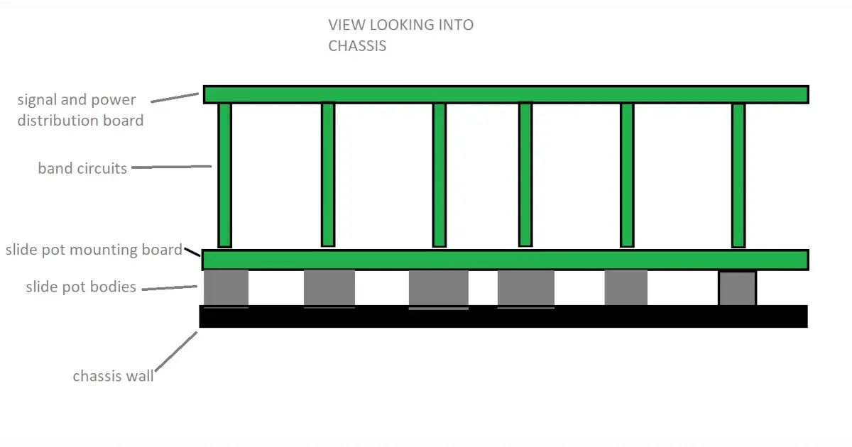
no, I mean, it'll totally work. It's, it's, they're not going to, it's not going to be an issue. The but that, but the thing about it is, if you space them that close together, then the circuitry for each band has to fit within a window of 10 millimeters. And some of the chips I can get in small packages, but some of them only come in like SLIC sixteens. And that eats up like the entirety of 10 millimeter wide. And so what that what that means is if you put all the slide pots in a row, all 20. And in fact, I have 21. So 20 of them act as cut boost sliders, and then the 21st one acts as the master volume, basically for the whole thing. So it's really 21 of these things. So this board is 210 millimeters wide by 48 millimeters high. And each slide potentiometer has a slide of range of 30 millimeters. So if you think about it, like if you line all of those potentiometers up, and then you slap one giant PCB on the back, you have basically no room to put the band on the back. And on top of that, there has to be a power supply with it. And there's other like ancillary stuff that happens with it, too. So I needed a different solution. And what I came up with was, I can use a PCI Express connector on the back of each one of these pots, because those are less than 10 millimeters. And then each band can be its own pluggable board that plugs into the back of this master like distribution. Gotcha on the back. So so so because the thing is I have space going into the chassis, I don't have lots of I guess, if you think about it, I guess that's like depth.
Yeah, you have a chance, but not X and Y. Yeah, exactly. Exactly. So.
So I started, I started designing around that, and that actually worked out pretty well. And the renderings, you'll see that I have a whole line of these PCI Express connectors. And one of the things that was interesting is I was originally designing everything around just doing some headers. And I realized that, in general, the headers that are readily available that have a datasheet. And that's kind of where the asterisk is, were actually ended up being more expensive than doing a card edge connection. thing. And mind you, I have to do this board 21 times. So any anything that I do, or any design decision I make instantaneously gets multiplied by 21. Right, yeah. So like I'm thinking about the overall cost of this, I want to build one of these things for my for this app that I'm designing, and I don't want it to get stupid expensive. And so if you go with a header solution, I didn't necessarily want to do a lot of through whole header stuff, I was looking more at surface mount stuff, it gets real expensive, real fast. And and that asterisk I was saying earlier about a pet or having a datasheet. Like I want to actually be able to design this thing. And I want to be able to model it. So I have to have some dimensional drawing. So in other words, I can't just go to Amazon or eBay and buy one of their grab bags of whatever had available. The I mean, technically I could but then it's becomes really difficult to make a footprint for it and becomes really difficult to make a 3d model for it. And so I wanted something that, you know, was available on Mauser. And so I found some, like I said, some PCI Express connectors that are card edge connectors. And what's cool is they already have a 3d model available, so I could just download it and dump it into Fusion 360 Which is awesome. I'm totally down for that.
Question. Yeah. So the so you have a backplane that goes across all the slide pots, right? Yeah. Yeah. Okay. And the slide pots are through hole. Yes. Are the is the PCI express slot through hole or surface mountain? It's through hole to actually so you're gonna have to I'm gonna assume you have to solder all the PCI Express first. Yep. And then the slide pot and you've made sure there's clearance between that all that stuff.
Not only have I made sure there's clearance fusion 360 is made sure there's clearance for me too. Oh, yeah, no, I double checked on all that. I honestly I spent about a week looking for connectors. And I know that sounds like a long time. But
if when you need to find the right connector,
oh yeah, that's connectors. Other words, we've talked about this multiple times, it's the worst searching for connectors, I spent more time searching for this one connector than I did designing the entire equalizer. So it's just that's sort of the way it goes. But I finally landed on one where it's not going to break the bank. And it works. Although I will, okay, let's, uh, let me let me talk about one thing real quick, the, the one of the boards, or the one board that is not a band for the EQ, it's basically the the volume controller and stuff, I'm putting all the power supply stuff on that module that plugs in. And so all the ins and outs to this entire sub circuit, the equalizer all exist on one of the modules. And that module then sends signals and power and ground and everything down to the main distribution board that gets sent to all the bands, and then all the information comes back. So basically, I'm making this whole big chunk of circuitry where it has one small board where everything goes in and out, which is nice. However, you have a bunch of signals, then that you have to pass down to this distribution board and get all over the place. So I've got a positive 12 volt, a negative 12 volt, I have a positive five volt reference voltage, which is just that real stable five volt, a negative five volt reference ground, a cut signal, a boost signal, a potentiometer pin for analog control, and then a ton of signals that all represent each band. And so it ends up being around 50 to 55 signals or power or ground or just individual nets effectively that have to flow around. And I realized earlier that I picked a 36 pin PCI II connector, because I was I was doing something well, I went down the path on a on a specific design that I just don't think that I'm happy with. And I'm going to change it now. Basically, the style of EQ that I'm doing is, is everything exists within a feedback loop, or two feedback loops actually, where one feedback loop, if you increase a potentiometer, then it one feedback loop takes over and you get a boost. And then the opposite is true if you turn the potentiometer the other way. And what it ends up, what ends up happening is you have the inverting terminal of an op amp B, one inverting terminal is the cut terminal, and the other one is the boost terminal. So I have 20 different signals going to one inverting terminal of an op amp and then 20 Other signals going to another inverting terminal. And I previously had it where that terminal was open and available to my distribution board my backplane board. And I realized that that's just not going to do well. That's just inviting noise and oscillation into the whole circuit. Yeah, and the reason why I did that is because I wanted to mix everything on the distribution board. But this the the signals are going to be they're going to be strong, but they're the impedance is really going to be hard to control. And there's parasitic capacitance and long trace length and all kinds of stuff, it's just, I realized that's just not gonna work well. So in other words, I can't take the 20 signals and mix them together on the distribution board, I'm going to have to take 20 individual signals, and send them across the distribution board. And in fact, 40 individual signals because I have 20 cuts and 20 boosts. So I'm gonna have to go from a 36 pin PCI up to the 64 pin PCI II, which I measured it and it's close it close in terms of like, it's, it's gonna be it's going to be a real tight fit in terms of my distribution port. But regardless, I think it'll all work out in the end. So
are you gonna go with the same family of parts, so you don't have to like search for another week to find?
Yeah, what's what's great is you change one number in the Part Number, and it goes from 36 pins to 64. And it raised the cost of each connector by like three cents or something like that. So basically, all I have to do is read download the 3d model and then change my footprint. And it's not magically have it. Yeah, so that was a mouthful. I know but like, that's kind of what I've been working on. So
have you gotten to I guess, I guess you haven't gotten to doing the beveled edges stuff then.
I actually so I did design In the the daughterboard that connects into the PCI connectors. So yeah, I have gotten to that point. Well, I was I was messing with that last night. It's just it's kind of it's sloppy. Right now. I haven't cleaned it up. I have a board outline. And I know where the pins are supposed to be. They're not really there yet.
So when you I guess when you finally get to that point, we'll have to talk about CAD design for beveled edges and hard gold fingers.
Yeah, cuz I don't think we've talked about that before. Like, yeah, how do you specify gold fingers? How do you specify a PCB edge connection? And how do you actually get one made? I think that's a good topic.
Yeah. Coming soon on a map near you. i So before we get to the RFO, we do have one question from the Slack channel. And is what beers should we consume? So that we can play along at home? I guess whatever. Beer is cold.
Cool. Okay. So that obviously, there's there's two rules to bear. before anything gets asked. The best beer is free. The next best beer is cold. And then you can start talking about all the all the details, right?
Yes, yes. So I'm currently drinking three nations haze wizard.
You know, I had to admit, I don't have a beer in front of me right now. But I'm battling a cold. So yeah, you have you have a beer is not a good exception right there. However, okay, so there is a there's an excellent beer that if you can get a chance to get it, I don't know if it's even available outside of Denver, but it's called pretzel assassin by Denver beer Co. I think that's Denver. Yeah, I
think it's, you've told me about this beer. It
does not sound Oh, it's delicious. It's absolutely amazing. So so if you can get your hands on some pretzels assassin do it.
So onto the RFO. So the first one is going to be debugging ICRC with hardware, which is kind of what you typically do. But this is a piece of hardware that makes it easier to debug ICE Core c, and it's called the ice square C Driver. And it's a crowdfunded piece of hardware and software package by James Bowman. It's an open source tool that basically can easily drive very high squishy devices. So it's like a little board, it's got a screen on it. And then it's got USB, so the USB hooks up to your computer. And then you hook up your I squared C device, like a breakout board or whatever, to this board. And you can send commands with a GUI or command line or you can like script it with Python or C plus plus. And you can basically you can see the commands, what's happening on the screen as well. So I think you can pause it with the GUI as well. So you can see what like, what the actual data is. And, you know, pretty interesting way of going about icecool see development.
Yeah, it's kind of it's cool, too, because it shows the voltage and it also shows the current consumption. That's that's flowing through it. And in the screen. I love it. It actually has two small little waveform to show what's going on. That's kind of cool.
Yeah, it's a pretty, pretty neat little device. I ordered one. I think it was like $30. Okay. So
if I mean, if you're if you're hammering a nice grade C all the time, then yeah, I
do tons i square C stuff. So I was looking at that I'm like, Hmm, that would be very useful for just like, instead of having to bang out code on, like, a pair up parallax propeller or a, if a mate just to see if hardware is working. I could use that instead.
Yeah, that's true. That's yeah, that's, that's a good way of putting it. Now. Do you prefer I squared C over spy? Or actually? And a secondary question? Do you call it spy or spy?
I call it spy. Okay? And I Scorsese just a protocol across spy. So tech,
yeah, if you want to get real technical it is, but people lump them into two different categories.
Yeah, cuz spy usually really means only one device is really on that bus. Unless you have chip selects.
Oh, I was about to say. Yeah, chip selects mean that it's not right. I
mean, technically, they're all Well, okay. That's a weird one there too. I score see though everything is just an address instead. So yes. So you don't need chips like so you save it? Oh.
Yeah, yeah. Well, and that's usually why it's been preferable because you fewer pins now.
So I would say I don't have a preference. I would. I usually prefer I squared C, because it uses less pins and thus there's less stuff the route unless it's like, like if it's Like a dedicated DAC or ADC, then I'll do spy like, I'm like, I'm only going to use this bus for this one part, or this one function than Yeah, Spy would be preferred that way not even wasting address, you know, having to send the address when you only have one device there.
Well, and generally spy is a lot faster, right? Then Then I do see
the pens. You have a more efficient data rate at the same clock speed, you have a more efficient data rate, because you don't have to send an address with spy usually,
have you ever run out of addresses with ITC?
No have nots. I have any conflicts before but not on my own stuff I've designed.
Well, I was working with a Mac's chip a while back that in the datasheet, it only had the ability to have three separate addresses. So and I could see a design easily needing more than three of these chips, which would just basically be like, well, sorry, you know, or I guess you could just do a different eye to see bus. But at that point, you're defeating the purpose, right?
Correct. Yeah. Yeah, I've seen that before, too. But I've never ran into my own designs.
Yeah, I guess I've never run out of it. I just, but I guess I guess if you're if you're specking, your design, and you wanted to use that chip, and then realized you couldn't then you just go find a different one. Right.
Yeah, basically. So I guess that's a good thing, if you're an embedded system designer, is looking at your chips, if there is square C and making sure they don't conflict on, you know, the the firmware bus that Yeah, yeah. So that's actually something the hardware engineers should be doing when they're designing the board, or at least the that's actually not even a board layout thing. That's a high level we are choosing these parts level before you even get to schematic layout.
Oh, for sure. But But also, I think that's an excellent time to write a note on your schematic like, especially if the address is set by like pulling pins high or low. Yeah, write the address as a note on the schematic. And then it's that much easier that I actually
do that I will write down like they have select pins, I'll write down. Basically I'll write down if I put the select 000. It's this address 001 Is this one,
etc? Yeah, yeah. And I've totally done that before where I've written the entire table on the schematic, where if later on, I need to go back and change something, I don't want to dig through the datasheet. Again, it's right there on my schematic. Yeah, so much easier
when we need to have like a collection of those little tiny, met tips,
hot tips by met.
Okay, so our next RFO is low cost, reverse polarity and overcurrent protection. And this was a video that Jeri Ellsworth put out earlier this week.
Yeah. So reverse polarity protection is actually a really great little video that Jerry threw together to talk about a couple of different methods of doing reverse polarity protection. And I love it because the first one she calls out, she's just like, well, one of the options is just do nothing. And trust that
you users will plug it to plug it in correctly every single time.
Yeah, well, and she has a she has a pretty good little like few second rant about, like, if something can be broken, your users will find it like it's just a guarantee. So she actually shows, she shows a couple of methods for reverse polarity protection. And she kind of like steps them up in I guess a sort of hierarchy. And she starts with just a diode input. So you know, if you put a diode right at the input, if you if you put your your power input backwards, then your your you reverse biasing a diode and it just won't conduct. So at sort of unless
you go over the reverse bias, voltage.
Well, D yen. I mean, nothing will survive that at that point, you know,
yeah, if your user is putting 500 volts across a 12 volt device, I mean, it, it's game over 30 Probably, you know, it's going to expect it to die. Right, right.
Right. So that's sort of like it's a brute force. It's a really cheap method, and it's not necessarily going to work well. There's a lot of problems with it. It's got heat, you have an inherent voltage drop. You have a single point failure, all kinds of bad things. So the next thing she talked about is the exploding diode, which is a reverse diode to ground such that if you put something in backwards then basically you're you're shorting your power supply through a diode or you're shorting your battery or whatever you do. It's kind of obvious to tell that's also not necessarily a good way of working you No having reverse polarity protection, mainly because you short your power supply, which is not necessarily a good thing. But also, you know, if you have that diode that does explode after it explodes, you're not protected anymore. So
really, you're protected for about 15 seconds. Yeah. heats up and start smoking.
What I've seen with those kinds of solutions is that, like, if you plug them in backwards, there's some kind of indicator that will also tell you that it's backwards.
It's or the device itself is not turning on.
Yeah, right. Right. And then you go and look. So that's another really cheap method. But then so there is
an extended version of that, that I've done before. That is a you put the diode backwards across the rails, right? Yeah, but you also put a in series to like the input or output, you put a PTC fuse, oh, that's rated very high, like your device is only going to use like a quarter of an amp. But then you put a one amp PTC, so during normal operation is not a lot of drop across it. Yeah. But when you're in reverse, it's going to dump a lot of power across that diode, but it will eventually shut it off that fuse. So you don't actually blow the fuse up.
Yeah, so pretty solid solution. And cheap, too, right?
Yeah, it's just one more part. Right? Right.
Well, and as with so many solutions like this, you know, as we're going up in the hierarchy, you're effectively adding one more part of each time, it's basically more complexity, right. And one of the more like, commonly accepted ways of doing this is with a P MOSFET. Right at the right at the input. So basically, the the P FET. acts as a switch that just will turn on when you have the correct polarity and will not turn on if you don't. And so it depends on how it's all excuse me, properly connected. But but you can, you can get really cheap, really simple reverse polarity protection with with a cumulus FET. And that's based mainly on the fact that FETs nowadays are incredibly cheap, they can handle a lot of juice. And when they turn on, you can find FETs that have very low rds, which is their internal resistance channel resistance. So it's like it's almost not there when everything's working properly. And then it opens entirely when things are not working properly. So it's, it's about the best you can get out of it. Yeah, I
generally designed with the P FETs. For reverse bias, polarity production.
Yeah, yeah. And just, yeah, I don't know, it's a pretty, pretty straightforward solution. There's a lot of information online. And if you just Google PhET, reverse polarity protection, there's just tons and tons of pictures of it. Now gerrae Also, she was talking about in this video, she was talking about a previous design that she was working on, where she was doing some current limiting so with, with a handful more voodoo, you can actually have it be reverse polarity protection, and you can do current limiting, and she actually tested and works out pretty well.
Yeah, I got to look that one up. Yeah, go
check it out. It's a short video, but, but it's a bunch of good information.
I did notice that she has a Robbie robot on her desk.
Oh, yeah, she does. And you know what's funny, when I when I first moved up to Denver, I went over to one of my buddies at work, and sitting right next to his dinner table. There's a Robbie robot right there that he bought his wife for Christmas, because she was she she liked it. You know, when she was a kid? And I was like, yes. Just look. Where's yours? That you know, I'm still unpacking it just because we moved like two weeks ago, so it's somewhere I have no idea where
Yeah. Oh, what's up? We should eventually design a map. Open Source Robbie robot style bot that you can 3d print.
That'd be cool. Yeah, yeah. And then you can learn how to save your pennies because people carry change and now eats ICS now we need a Robbie robot that somehow eats bitcoins
eats digital currency.
Yeah. Blockchain Ravi robot
do you have anything else Steven? I think that's last RFO I think that's it. Yeah, so that was the Mac Feb engineering podcast we are your hosts Parker Dolman and Steven Craig. See you next time guys.
Take it easy
Thank you. Yes, you our listener for downloading our show if you have a cool idea, project topic or right Be robot story. Let Stephen and I know Tweet us at Matt creb at Longhorn engineer with no O's, or at analog E and G, which is Stephens, or emails that podcast at Mac fab.com. That's probably the easiest way because trying to remember all those other ones is probably a lot harder. Also check out our Slack channel. We hang out in the Slack channel all the time, talk to our listeners, we suggest cool project ideas, find cool parts posting there all the time. So that's kind of like the map after hours. And if you're not subscribed to the podcast yet, click that subscribe button. We have a new mailing list for the podcast. So go to Mack fab.com/blogs/podcast There'll be a annoying pop up that will pop up, type in your email address, hit submit, and you will be on our new mailing list. And so that way you get the latest episode right when it releases and please review the podcast wherever you listen. It helps the show stay visible and helps new listeners find us
The Venti-Q gets nears completion, USB Type-C example circuit completed, and EE interview topics.
Parker talks about his Embedded System Design process and Stephen explains his 20 band EQ design!
Parker wraps up his Wagon Chime Module and looks at USB Power Switches and Stephen covers his EQ build.