Related Topics
Let’s Segway into the Next Topic
AI and ChatGPT have been in the news about how it will change world views or will it be relegated, making sure NPCs in video games don’t repeat dialog?
The Wheels Are Finally Off
How easy is it to make a retro gaming console? Stephen breaks down his design and build criteria that involves no custom PCBs.
Mastery of Skills and Wonder
Parker and Stephen chat about the recent Nintendo Switch hack and Stephen moving to Colorado.
Other Resources
Circuit Break Podcast
Webinars
Videos
Tour MacroFab's ITAR-Compliant Facility
May 23, 2018, Episode #121
- Stephen
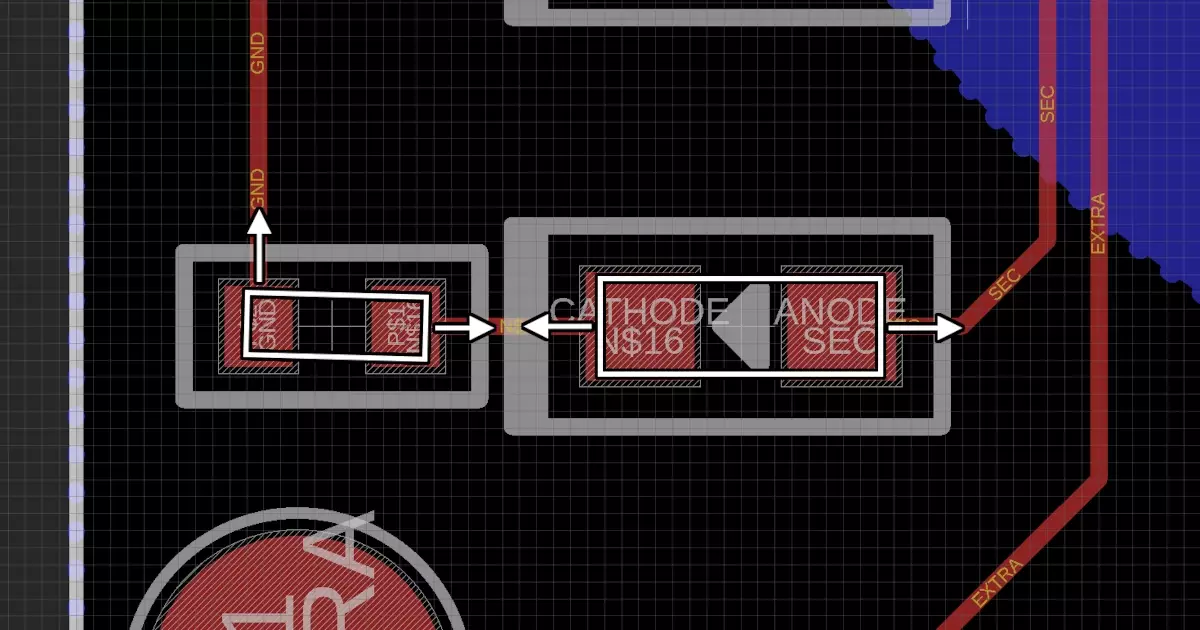
- Mute circuit design
- PDF of the schematic
- Is it really digital or analog? What is the defining difference between the two
- Mute circuit design
- Parker
- Gameboy VGA project
- Added SN74LVC8T245 level shifters
- Designing a flat flex cable?
- Will document it on his blog
- Left to do on the schematic side of things
- VGA connector
- Possible L717HDEH15POL2 part?
- 3.3V TTL -> Analog VGA signal
- Going to use a resistor ladder
- Current dev board uses 4bit VGA with 500Ω, 1kΩ, 2kΩ, and 4kΩ ladder
- Serial Terminal? Never have done this in verilog
- FT230X to USB
- VGA connector
- Brewery wiring
- Gameboy VGA project
- R.F.O.
- Summer projects ideas for senior in computer engineering
- Car counting and just designing a PCB
- SSPS update? 🙂
- Summer projects ideas for senior in computer engineering
- Announcements
- Twitter Chat Info
- May 25th Friday at 1PM CST
- Use #MacroFab to join the conversation
- MacroFab Monthly Electronics Meetup
- May 23rd 6PM at MacroFab HQ in Houston
- Brandon Satrom from Particle. Going to give a talk about IoT fundamentals.
- We will stream it on Twitch for non-Houstonians
- Houston Hardware Happy Hour
- June 7th at Slowpokes
- Bring hacks and hang out
- Twitter Chat Info
Visit our Slack Channel and join the conversation in between episodes and please review us, wherever you listen (PodcastAddict, iTunes). It helps this show stay visible and helps new listeners find us.

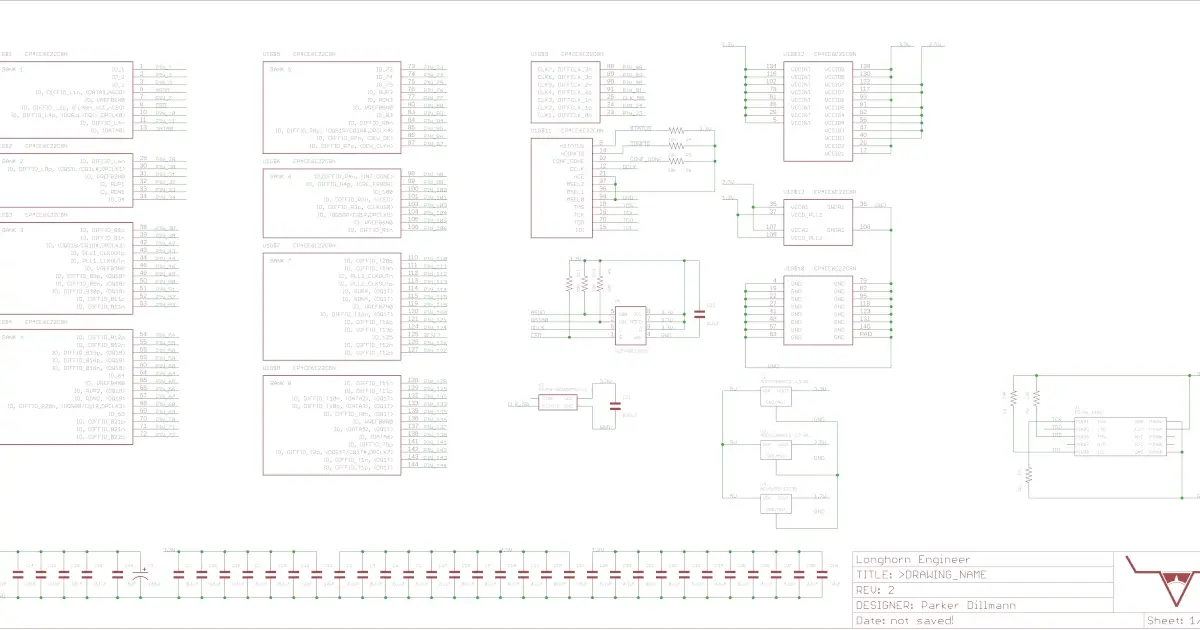
Level shifters for the Gameboy VGA project. Uses the Ti SN74LVC8T245PWR.

Current state of the first project that was on the MEP. The Super Simple Power Supply.
About the Hosts
Parker Dillmann
Parker is an Electrical Engineer with backgrounds in Embedded System Design and Digital Signal Processing. He got his start in 2005 by hacking Nintendo consoles into portable gaming units. The following year he designed and produced an Atari 2600 video mod to allow the Atari to display a crisp, RF fuzz free picture on newer TVs. Over a thousand Atari video mods where produced by Parker from 2006 to 2011 and the mod is still made by other enthusiasts in the Atari community.
In 2006, Parker enrolled at The University of Texas at Austin as a Petroleum Engineer. After realizing electronics was his passion he switched majors in 2007 to Electrical and Computer Engineering. Following his previous background in making the Atari 2600 video mod, Parker decided to take more board layout classes and circuit design classes. Other areas of study include robotics, microcontroller theory and design, FPGA development with VHDL and Verilog, and image and signal processing with DSPs. In 2010, Parker won a Ti sponsored Launchpad programming and design contest that was held by the IEEE CS chapter at the University. Parker graduated with a BS in Electrical and Computer Engineering in the Spring of 2012.
In the Summer of 2012, Parker was hired on as an Electrical Engineer at Dynamic Perception to design and prototype new electronic products. Here, Parker learned about full product development cycles and honed his board layout skills. Seeing the difficulties in managing operations and FCC/CE compliance testing, Parker thought there had to be a better way for small electronic companies to get their product out in customer's hands.
Parker also runs the blog, longhornengineer.com, where he posts his personal projects, technical guides, and appnotes about board layout design and components.

Stephen Kraig
Stephen Kraig is a component engineer working in the aerospace industry. He has applied his electrical engineering knowledge in a variety of contexts previously, including oil and gas, contract manufacturing, audio electronic repair, and synthesizer design. A graduate of Texas A&M, Stephen has lived his adult life in the Houston, TX, and Denver, CO, areas.
Stephen has never said no to a project. From building guitar amps (starting when he was 17) to designing and building his own CNC table to fine-tuning the mineral composition of the water he uses to brew beer, he thrives on testing, experimentation, and problem-solving. Tune into the podcast to learn more about the wacky stuff Stephen gets up to.
Special thanks to whixr over at Tymkrs for the intro and outro!
Related Podcasts

The Wheels Are Finally Off
How easy is it to make a retro gaming console? Stephen breaks down his design and build criteria that involves no custom PCBs.
Mastery of Skills and Wonder
Parker and Stephen chat about the recent Nintendo Switch hack and Stephen moving to Colorado.
From A Current Perspective
Parker talks about revitalizing old projects, Stephen discusses all pass filters, and side entry into SMT pads.

Let’s Segway into the Next Topic
AI and ChatGPT have been in the news about how it will change world views or will it be relegated, making sure NPCs in video games don’t repeat dialog?
Standard-ish
Stephen hacks an oscilloscope into a dynamic signal analyzer and Parker gets some verilog code to compile.
Interview with Ben Heck of The Ben Heck Show
This week Stephen and Parker have Benjamin Heckendorn of The Ben Heck Show as a guest!
About MacroFab
MacroFab offers comprehensive manufacturing solutions, from your smallest prototyping orders to your largest production needs. Our factory network locations are strategically located across North America, ensuring that we have the flexibility to provide capacity when and where you need it most.
Experience the future of EMS manufacturing with our state-of-the-art technology platform and cutting-edge digital supply chain solutions. At MacroFab, we ensure that your electronics are produced faster, more efficiently, and with fewer logistic problems than ever before.
Take advantage of AI-enabled sourcing opportunities and employ expert teams who are connected through a user-friendly technology platform. Discover how streamlined electronics manufacturing can benefit your business by contacting us today.