Datasheets are usually an engineer's friend. However, Stephen finds that his rotary switch's datasheets do not match the physical device.
What separates good documentation from bad and which kind of application notes do you like? Also, Ancient Chinese Semiconductor 7-segment drivers!
Parker is an Electrical Engineer with backgrounds in Embedded System Design and Digital Signal Processing. He got his start in 2005 by hacking Nintendo consoles into portable gaming units. The following year he designed and produced an Atari 2600 video mod to allow the Atari to display a crisp, RF fuzz free picture on newer TVs. Over a thousand Atari video mods where produced by Parker from 2006 to 2011 and the mod is still made by other enthusiasts in the Atari community.
In 2006, Parker enrolled at The University of Texas at Austin as a Petroleum Engineer. After realizing electronics was his passion he switched majors in 2007 to Electrical and Computer Engineering. Following his previous background in making the Atari 2600 video mod, Parker decided to take more board layout classes and circuit design classes. Other areas of study include robotics, microcontroller theory and design, FPGA development with VHDL and Verilog, and image and signal processing with DSPs. In 2010, Parker won a Ti sponsored Launchpad programming and design contest that was held by the IEEE CS chapter at the University. Parker graduated with a BS in Electrical and Computer Engineering in the Spring of 2012.
In the Summer of 2012, Parker was hired on as an Electrical Engineer at Dynamic Perception to design and prototype new electronic products. Here, Parker learned about full product development cycles and honed his board layout skills. Seeing the difficulties in managing operations and FCC/CE compliance testing, Parker thought there had to be a better way for small electronic companies to get their product out in customer's hands.
Parker also runs the blog, longhornengineer.com, where he posts his personal projects, technical guides, and appnotes about board layout design and components.
Stephen Kraig began his electronics career by building musical oriented circuits in 2003. Stephen is an avid guitar player and, in his down time, manufactures audio electronics including guitar amplifiers, pedals, and pro audio gear. Stephen graduated with a BS in Electrical Engineering from Texas A&M University.
Special thanks to whixr over at Tymkrs for the intro and outro!
Welcome to the McAfee web engineering podcast. We're your hosts Parker, Dolman
and Steven Gregg.
This is episode 277. Okay, so last week, we brought back the tasty chips segments. I think that was like the first time we've done that. A second a named segment and like 100 episodes, something like that. It's
been, it's been a hot minute. And tasty chips cache, what was the genesis of tasty chips?
It was.
It was we were coming up with a chip company, right
chip company. Yeah. And each part number would be an M, but a sequence of M's. Like tasty chip? That's right. The first chip would be n one. Yeah. The second will be two M's, three M's, etc, etc.
It's like that crash test dummy dummy song where the name of the song is 12 letter M's? Just
huh. I did not even know that. The crash test? Are you talking about the TV show? No, no,
it's abandoned the night.
There was a crash test dummy TV show? Oh, yeah. I
mean, that was a cartoon back in the day. Yeah. Yeah, here, let me I'm gonna I'm gonna this song is both awesome and awful at the same time, where you're putting it, putting it in our Twitch stream? Yeah, good. Just go look at the name of it. It's just 12 letter M's. And that's the chorus as well. So go listen to that sometime.
Okay, I'm not going to put it in our Hey, they
could be that could be the theme song for the tasty chips company.
So this week, I found actually, I have two because they're kind of the same. Similar kind of ideas. Harwin has a product called Easy cable clips. That there's a DigiKey link right there. I need to check this out. These are like surface mount clips that you could put on your board that you can route wires on?
Oh, so you just slide the wire into it. And the clients are closed? Oh, that's cool.
Yeah, I don't I don't have any products that would ever. I've ever designed that. I'm like, Oh, that would be such a good solution for but I could think of like if you have a wiring harness that comes on your board, or any kind of like high current power routing that you want to use, like an external cable for this would be perfect for?
Yeah, I was thinking because in one of my amplifiers, I do have some off board wiring. But I designed everything such that all of my connectors are right on the edge of the board. But because I was thinking this could be really useful, but not in this particular product. I'm curious though, does this come on a reel? Yeah, they come on reels. Okay. Yeah, tape and reel. That's cool.
I think this is one of those products that when you look at him, you're like, Oh, this is such an awesome idea. But none of my current ideas would benefit from it. It's one of those, you've just added another tool to your toolbox of like, product design. Like, oh, now I know this thing exists. So if I have a a problem with my assembly that can be it can be solved with this component.
Yeah, yeah. So I mean, if for some reason your design requires say, a jumper, that is that goes across your board. So it terminates, it begins and terminates on your board, these could be really useful for that. Yeah.
And then the other one very similar, is from a company called Mac eight. And I think it's a, that's a Japanese company. And it's their CZ series, wiring clips for surface mounting. And it's like for multi PCB assemblies inside of a chassis. This gives a place for wires to kind of like rest on. So like, if you have a wire, a wiring harness that runs across a bunch of boards, you could put these like hooks on your, on your board on your PCBs, and then the wires can just hang in there.
That is that seems incredibly specific. It's
very, but it's like now you've put that tool in your toolbox now and you're like, oh, okay, now if I ever design anything that's like this, I need to have a spot for like this wiring harness delay. Bam.
Yeah, yeah, I could. man these are great. This is this is like This is next level in terms of, like a lot of us in terms of designers, we think of the board. We don't necessarily. We're not necessarily experts in the system. This is the guy who knows all the system tricks.
Yeah, this is a system level system product level assembly. Yeah. That really this MAC aid company looks like they have a lot of cool stuff. So I'm gonna dive into the website later. But um, yeah, they got some cool stuff. And
I'm curious, can you share while you're looking at these kinds of things?
I actually just I found the Harwin easy cable clips for what was I searching? Oh,
and then just started diving into it? Yeah, I
just I, those are not parts I was actually even looking for. By found one of my favorite things I've been doing now to find components like, especially like weird connectors and stuff is just throw it into Google image search, and then just go through Google image search and see if I find anything that looks interesting, or might solve my problem. And those were popping up. And I clicked on them and like, oh, yeah, that'd be pretty interesting to share on the map.
Okay. Yeah. I was just curious if you had some kind of cool project that like,
No, we're cable management. Now, I want to build something that has these now. But it's very interesting that that's become my favorite method of searching for parts. Now weird parts? Is Google image search.
They are I know, it's somewhere on there. I should probably know this better. But Digi key has an image search as well. Whereas you can go to connectors and say just show me pictures of connectors. And then you can just start looking around, which I think is cool. I haven't tried that yet. It's I've done it once or twice. Luckily, I haven't had to do much hardcore connector searching. Recently I've gotten I've got my bag of tricks. And I'm holding on to those really saying no, like, these are my connectors. I don't want to go search for more right now.
But what I really like about the this Google image search method is when you'll search, just search for some keywords, and then make sure to put like PCB in there or something like that, or panel mount depending on how you want to mount them. But when you click an image on Google, I mean, everyone's usable. I'm hoping most people use Google image search. But when you click it, the image, you get a pain that's like related images to these, which I don't know how to like come up with those. But that allows you to like go out and like a level deeper into that kind of thing.
You know how you know how they figure that out? There was just some captures somewhere around where they were like, which ones of these are connectors and people have been training campus on connectors.
Actually, I watched the thing the other day. That was funny. It was all about catches in the recaptures, and like the new catches in. AI has gotten more reliable at selecting images than humans are now. So it's no longer a test of Are you a human. So we're having to, I don't know, go to whatever the next level caption is. All right. So a few weeks ago, maybe it was actually only just two weeks ago. Time moves crazy. Now, the I've been working on that rotary switch that new 24 position log,
a logarithmic encoder, resistor network thing thing,
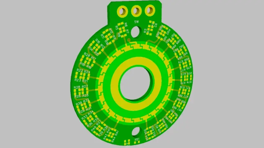
right? Yeah. So I am like 99% of the way done with the with the PCB. So that last 1% is kind of like just nudging things around and adding cosmetics and things. So I've been playing around with getting that uploaded to the Mac Feb platform. And this is totally not a sell for the Mac fair platform. But it's been probably two years since I've uploaded something to it. I mean, I work at a contract manufacturer with with most of the capabilities that macro fab uses so like I just haven't had a huge need for it. But I'm like hey, I want to I want to load this one up on on macro FEM which that's that's been fun because you guys I mean things are things are different now than when they were especially for dip trace because what dip trace now you guys accept it interpreted it interprets dip trace a lot better than it did in the past. There was always some like tricks I had to do to make it work. Also, the Bill of Materials seems a lot easier to navigate in us this time around. So pretty cool. Like it's fun to take like big breaks from looking at macro fab. And then like, just jump in and be like what's new and see all the all the new stuff with it. Once again, I'm totally not trying to sell microphones here, this is legit, like I've been playing around with it for, for fun. So I the schematic and the layout and my simulation, I've put up on my GitHub, if anyone wants to check out this project, it's, that's github.com/analog EMG. This, the simulation is literally just like a huge long string of resistors. In fact, it's 92 resistors in a in a in a huge pattern. So if you want to check that out, you know, have fun with it. And for those who don't know, I guess I should just back up, I'm making a rotary, logarithmic attenuator for a project I'm working on. It's a 24 step rotary switch, where each step is one dB attenuation. And the whole purpose of this is such that you can have recall, hardware recall, if you like a setting, you can write down the number and then actually return to that as opposed to having theoretically infinite rotation potentiometers you can actually go to a particular step.
And you even like, took a logarithmic, logarithmic and quotes potentiometer. And then they're not logarithmic,
not at all. They're two linear curves, but that not even curved lines to two lines that approximate
logarithmic. Yeah, they're best fit. Yeah, yeah,
good enough, let's. So I ended up with 49, unique resistor values for each one of these. So I feel bad. If I get macro fab to make these because 49, that means 49 feeders are dedicated to just
that would fill up half a half a machine, right
for just this one thing. So I'm sorry, but that's just the way it is. In this case, it's 49, unique resistor values, and a total of 92 resistors. on there, and what what, what I had some fun with it, I ranked all of the resistor values. So taking one step back, I use an online calculator to calculate series and parallel resistance of sets of four resistors to make these really ridiculous resistor values that are three decimal point, precision. So it'll be stuff like I need a resistor that's 1,623.4 to six ohms. And I use this calculator to get that bang on. And I let the calculator run free. And do like I don't know how many iterations until it finally finds whatever combination finds exactly that. And so at the end of it all, I plugged those all into my schematic, I printed out my bill of materials, and then I rank them based off of usage. And I wanted to see what is the most used resistor, if you just go through a bazillion calculations, which one shows up the most. And I'll preface this by saying like, this doesn't necessarily mean anything. And most of my resistor values are lower in value, like they're between, say, 100 ohms, and, like 2k, or something like that. So your mileage would would vary on that. But it's still fun to just kind of do some statistics on it. And the number one resistor that happened out of all of these calculations is 5.6k. For some reason, 5.6k got us the most in series and parallel to work all that out. I would, it would almost be fun to let that calculator, like run for a bazillion iterations of a ton of different variables, and then see if there's some kind of pattern that appears that is based on the algorithm of that calculator, or it's based on just reality, maybe 5.6 or 56k, or 560k, or whatever ended up being like the most optimal value if you need to series parallel something to get something else. Like if you want it gives you the most flexibility, they give you the most flexibility I don't know I mean, because I've we're only talking about 92 Total resistors on my product here, but it got me thinking about that because it was used like significantly more than any other resistor on there. I don't have the statistical were about to go through and do something like that, because that sounds brutal. That sounds like a lot of work, but I don't know it would be really fun because then at that point, like if you had like a kit of resistors you should just always make sure you have that available. Or and the number two and number three resistors were 330 R and 470 R so I don't know, there's no real significance there.
Well, what's interesting is I do see a lot of 5.6k, a lot of 330 and a lot of 470. So that's kind of interesting. I wonder why. Now, most of the applications I see are not this at all. But I wonder why that is? Yeah, I don't know. I wonder if that plays into like, normal voltages for for like, power rails, like 3.3 volts, five volts, etc. And then like, 10 micro amps or something like that? Well, it'd be,
I think, I think us as engineers, we've made a lot of rule of thumbs that have just leaked out to other people like bypass caps, what's the value?
Point one micro farad?
Exactly calculated? If you? Yeah, like you could? And maybe you should, in some situations, but in general, like, how many people just take a shotgun filled with zero point ones and pointed at their board? Like me? I do everybody, right. Like
it? Well, we actually talked about that on the previous episode, like, years ago. And it's it's point one is overkill for bypass gaps. But thing is, you know, what's going to work and point one microphones are the cheapest.
But are they the cheapest? Because they are, because everyone just uses them?
I think that's what it is, though. Probably. Right.
And how about pull up resistors for itu ITC lines? Like, what are their normal values?
4.7k.
Exactly. Virtually everyone uses that. That's another one, though, that that could be calculated, right?
Yeah. The optimal one gave you the right was the right rise time. Yeah.
Yeah. Yeah. But I would almost I would almost wonder if like 4.7k resistors sell out more at at the big players?
Or they just have more of them. Right, right.
So in this in playing around with this PCB, and actually what I've been doing recently at work, I ran into a bug, with with dip trace by EDA tool of choice. That is interesting. And I was talking with my boss today about it, because I just ran into it. But apparently, he's known about this for a little bit of time. Something that I don't normally need to do is define surface mount pads as having no paste.
Like, okay, 99%, not nine, yep, almost virtually always, if I have a surface mount pad, there's something going on. And I want paste going there. So I usually let that dip trace handled the default workings of do should there be an aperture on my stencil or not? Should I put paste on there? I think it's reasonable to trust your the EDA tool with that, especially once you've built up your libraries, and you just, you know what the shrinkage and everything should be. But I've been working with this rotary switch, which has wipers, and I'm doing evening plating on on these pads that I've got, I want to make sure that my wiper, and each one of my steps doesn't have any paste on it. If I send this off to somewhere, because the worst thing ever is if I got a bazillion of these made, and then, you know, like had people put up with 49 unique resistor values on a thing just to be like, well, they're completely worthless. Because if I if I got paste put on any of these pads, and at the same time at in my day job I'm working on SNAP dome actuator, switch designs, that those require exposed pads with no paste on them. So I've been needing to set up their trays such that I can have no paste on my pads, which is very simple. You can just click on a pad and say no paste. Done like it works that way. But what I've been wanting to do is is create a footprint where the footprint for that part is defined to have no paste such that if you bring it into a new always never have always have that and like okay, that sounds really reasonable, right? So here's what I found. That's kind of ridiculous. If if you do that and you save your footprint, where all of your pads that you don't want pace, you define them as no paste and you bring them into a new schematic. And then you bring that schematic over to a new board. Everything works great. You'll have no paste on that show up. But if it's this is an old footprint, if this was a footprint that even you made five minutes ago, and you go and you save that footprint again, what if you make that change at that footprint, and then you try to update your footprints all the way through, it doesn't pass through. Dip trace doesn't for whatever reason, doesn't suck that in. So effectively to get around this you have to do it right The first time you have to create your footprint right the first time, you have to bring it into the schematic right the first time. Everything else works about it. This is this is just a bug where that one attribute doesn't get this doesn't propagate, doesn't propagate forward, which interesting really blows because I created a footprint a while ago for these things. And I had pastes that had paste on it. And now I need to go and update it. And now I kind of have to restart on both schematic level and board level. And one of our products has almost 100 of these, I can't just click them and say update, I have to literally go delete them, go create them a new, bring them to the PCB, delete them, create them a new and it's just like, ah, that defeats the entire purpose of having like, connected and linked things. So and it's funny, like I said, my boss was like, oh, yeah, that's been around for a while. It's just, I've never needed to deal with it. I was banging my head on a table this morning. Because I was updating bringing it all the way through and it wasn't throwing any errors or anything like that, but nothing was working.
Have you thought about us? I wonder how well the ending is going to last summer this wipers
hard gold is the correct solution. Yes, Enid won't last forever. But I'm not concerned about I think it'll last plenty long. Mainly because these things won't get a massive amount of youth. Like if I was making this a product to go out the door, it'll get hard gold. In fact, all of the actuators that we're doing for our for our buttons with the snap domes, those are going to get our gold plated. But for me as a home gamer and you know, just spin in a thing around it. I don't have any concerns about it.
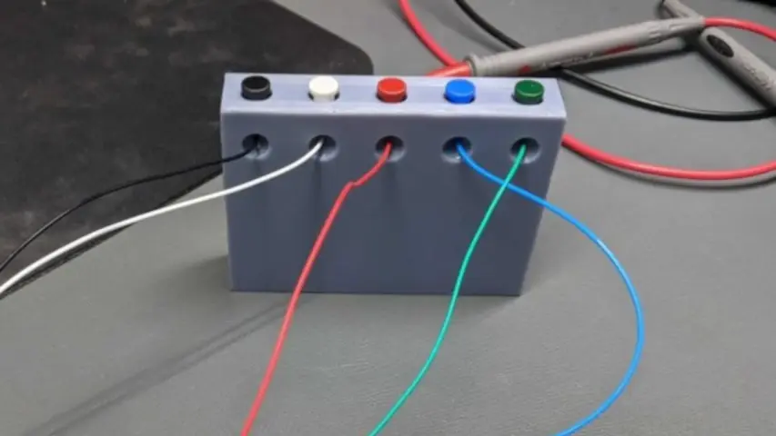
So last week, I talked about the it was last week's tasty chip, which wasn't a chip at all was the actually this week's isn't chips at all the clips, Chip clips. There was the easy hook installation piercing wire clamp. And unfortunately, I don't have a a better one here, but I spent some time and I made a installation block.
Oh, this is the thing where you can just press the buttons right and then insert your wires. Yeah,
so I'll take some pictures for the blog. But and they're even color coded the wire color. But you press this down. You can stick your wire in there. And then you just release it and it automatically pierces the wire and makes the connection.
That's really cool. Did you print that with your SLA printer? Oh, yeah. Nice.
That printer is just it's my new favorite manufacturing story right now. My Ivan like made little concave jumpers chamfer so that you don't have to get the wire perfect. Like you don't have to thread the needle, you can just jab it in the direction of the hole and guides it in. Yeah, yeah. I'm, I'm super pumped how well this turned out. And this is the thing about Steven, you gotta get a 3d printer I want to convert you eventually, is it I spent 30 minutes design this infusion and click Print on my printer, and an hour and 30 minutes later,
this was done. You got a nice little jig.
So in two hours, I went from an idea to something that actually functions and I was able to test it and validate it. It's just I think the thing is with 3d printers, between 3d printers, you could easily make this on a CNC except that you'd have to machine it, flip it over and do a bunch of fixes
that would be that would be a full day's work.
Yeah, it's just it's the it's the setup time is with 3d printers. There's just just very little sub time I wish you'd say how are things done?
You knew the 3d printing features from fusion?
No, not yet. Okay. You just export that as like a SD I export as an STL STL and then which is just a mesh file and then I bring that into whatever slicer, I use cura for my FDM printer. And then I use CIT box. I think it's what's called Okay, c h i t bo X. I think it should to box, c h i t UBox. All in One SLA slicer. Cool. Because the slicer just works differently because instead of making a tool path, like a G code tool path, it's makes a series of images it makes it more your Yeah, it's a movie that's a movie of your image one layer at a time. Yeah. So
yeah, I'll just go ahead and package up a 3d printer and ship it to Steven Craig Denver Colorado and and then I'll play with it and let you know if you converted me
there Yeah. Here that 3d printer companies out there Steven wants a sponsorship.
Yeah sure. Why not?
So that's that that's super cool that the isolation fixture thing because the high voltage on those
wires right
300 volts. Yeah. The and then last week, I was trying to find a solution for a comport like a serial comport, snooper, slash sniffer on Windows. And I ended up using the tool free serial analyzer.com, which sounds like that old what? Free credit report.com commercial. And it's interesting, because like, when you go to that website, anything that has free in it on the internet, it's not free. And it's like loaded with ads or whatever, seems to be fine. From like, it doesn't have any ads in it. Like, I can't even figure out if there was a way to like pay for it or anything.
It sure is not contacting the mothership underneath the hood. Yeah, I
have no idea. Maybe it's just like skimming my comport and sending that over to like Russia or something. Who knows,
with the hope that a credit card number goes across
your marriage we know is talking, sending my credit card information over cereal. But yeah, that that actually solved my problem. Because what I wanted to do is like, I just wanted to like look at the buffer and be like, okay, my Python serial script is sending this thing out into the world. And it will just dump the bytes out. So I'm like, okay, and then what am I getting back? What are the bytes? I'm getting back? And it does so without interfering with the Comm port. So like the program's talking don't know what they don't see the sniffer. So it
just has a send and receive buffer effectively, that shows you what's coming in and out. Yep, that's cool.
And it has way more tools to and that's built in. But that's what I was using for. It's like, you click the comport and then you can there's a whole list of like different tools that you can latch on to that comport. And the one I was using was just called data. And you just see the raw data packets.
I do they show up as binary or how are they does however
you want to play it, you can pick it, I was looking at it in bytes. hex code. Okay, got it. Because I was looking at like, eight bytes at a time, like the packets were only eight bytes long. But I was able to like, oh, like I was able to go, okay. My python script was not sending out the bytes correctly. And so I was able to actually see that in this code. And I'm like, okay, that's why my device is not responding correctly, because I'm not.
So it was it was your side, not the saw the hardware side?
Yeah, yeah, I knew it was on my end. I just couldn't figure it out. It's it was like debugging in the dark, though. Because like, you send out calls using a module called PI serial, and you send out the bytes, like through a REIT. And you're like, I assume it did it right. I assume I set everything up. Right. And nothing's coming back. So I must have done something wrong. Maybe.
Right. And then you accidentally set your current limit to none. And yeah, and you blow something up, right.
Yeah, exactly. So I have no idea. But yeah, so I was able to basically debug my software with that tool. So you see, you're talking skipping now. Right? Yeah, talking Skippy. And that's a next thing is got all the meters, all that stuff working great. Been testing a lot of stuff. And I want to expand how much stuff I'm testing with this product. And I need to automate testing clock drift. And what's interesting about this is I need to analyze the clock drift coming back from the from the DT the device under test, but not when I talk to it. So like my signal going out to it is in the same frequency as it coming back. I'm basically I'm analyzing the signal coming back from the device. And I can do it manually, which is what I've been currently doing. And how I do that is I have a scope. And I put it into AC couple mode, because I don't care about the DC and it's actually like, it's like a it's like a 300 volts signal. So I'm like, I don't care. It's 300 volts. I just want to I just want to see the waveform right now. Um, then I do like, a 10 volt trigger, and then hit single shot, son to come out to make the device talk. And then when it comes back, I get the packet, the big packet, and then I zoom into the packet and then measure the frequency. And then that frequency is like, I have a reference frequency, I just, I get the percentage difference. And to make sure I'm within that tolerance, that SLO
is this application for downhole communication. Maybe. Okay, got it. Yep.
And so I think I'm going to try automating the scope to do that. But is there a better way to look at that signal and analyze it? Is there a better tool, I should say? Because a frequency counter, like on a DMM doesn't work? Like the signal? If it was a continuous signal? You could do it with that. But it's not a continuous signal. And it's modulated. So you? Yeah, a DMM is just not fast enough to frequency count that so
so the test, you're you're saying here, you spit out just any command and you want it to respond? And what you're looking at is the frequency drift in just the amount of time that it responds, or over long periods of time?
In response to get back? Hmm, okay,
there's an expectation that it will drift at all, in that amount of time.
It's, it has to hit a certain frequency. And so let's say it's like 10 kilohertz? Well, you when you get that back, it's not gonna be exactly 10 kilohertz, it's gonna be 10 point something. And they want to know, how far off is that
off their actual reference interesting.
And so I had to measure that frequency. And so right now I do kind of manually with a scope. And I can probably automate that with Skippy I've been looking through the siglent programming for the their scopes. And it's like 115 pages of commands that I could send this thing. And I have a manual process that I've written down that works all the time, which is great, because now that you have a flowchart of a flowchart, and I can I can implement that into Skippy. But I'm just wondering if there's a better tool that can basically do a watch, I need to capture the waveform, and then analyze the frequency of that, I have actually even looked at doing an FFT of the signal, because you pretty much only had to, you have a zero and one to the modulation. And you can do those are two spikes on FFT. The problem with that is the oscilloscope that I have your FFT resolution is not high enough to get you within the tolerance of what you're actually checking for. Maybe a signal analyzer could actually have that resolution. But a signal analyzer is way more expensive than just measuring the frequency directly with the scope,
I think you need a frequency counter, a frequency counter that that can be talked to over Skippy. So you could set it up for a trigger, and most pulse counters or frequency counters, you can get they have like a window, you can say like, you know, count within X seconds or something like that. And I bet you a modern one, I haven't played too much with them. But I bet you a modern one. That could be over Skippy as well. So you have a trigger. And then it'll just within a certain frame window, it can count, however many pulses it snags. And that's probably your most accurate. Yeah, probably far more accurate than then a scope. Actually.
I'll take a look at that. Yeah,
you could actually, I wonder if there's Yeah, probably a Pulse Counter that once it sees the first rising edge, it begins its count. And begins a timer at the same time. I bet you Well, the thing is
there's in that that packet that you get back, there's actually two frequencies in there. And it's what makes it a little tricky. And you can measure either one, two, it's reference and because they're both derived from the same clock on the on the device. So is it like carrier modulator thing? Yeah, basically got it. And so you have like a zero is one frequency and a one a one is another frequency. And so you have mixed frequency in that packet. So I don't know if a simple that's why like one of the reasons why the DMM frequency counter that's built in just doesn't work. because it's it counts the whole thing. And it's just like, it basically averages it. You can't tell it to look for a small enough window because it doesn't know.
So, so split the signal into high pass the hell out of one low pass the hell out of the other sets. That one's only reading the carrier. One's only reading the modulator unless they're close in frequency, which they probably shouldn't be.
Yeah, I wonder if you could,
or put a notch filter, like make a little box with them with a really hardcore, negative infinite, theoretical knotch filter at the modulator such that the you can just read the carrier. I mean, that would require duplicating things. But but then you could you could, you know, get really accurate of each. That might be Yeah, that's probably it's a little bit more expensive. But that would be kind of definitive. If you did a knotch and said, only allow the zero frequency to come through. Yeah, yeah, that actually might be the way to do it. Yeah, that's yeah, because you only need to measure one. Oh, okay. Yeah, if you only need to measure one notch, the living hell out of whichever the other one is, and you'll get a pretty nice wave or the other. If we're talking about communication here, which were sort of maybe not like, the modulator and the carrier should be separated well enough away that you can filter one out and not heavily affect the other one. Yeah. The play with it? Yeah. And in fact, you could probably do that passively. Yeah, actually, yeah, of course, you could do it passively. You've got 300 volts available. So even if you have like horrible insertion loss, you still have more than enough signal to beat.
It's a pretty strong signal. It's a signal. It's like a peak the peak, it's like, well, 300 volts that offset? I think peak the peak is 30 to 40 volts.
I mean, still,
it's a pretty, pretty chalk signal.
Yeah. So say yeah, say you, you lose like 90% of the you could still get away with with reading it with standard test equipment. Yeah, that's probably your best just just build a passive. I mean, that'll be fun, because you have to build a passive knotch filter that uses high voltage components.
Yeah, I want to see how far I get with the scope method. And because I haven't done any of the Skippy stuff yet with it. And that works already. Don't so like my idea with that is basically capture the frame. And it's, I can always capture the frame, and then move to a certain section of the frame. And that works reliably, and then measure the frequency. And then basically, it was it. You know, it zooms in, that's not what it's doing. But it zooms in to that section of the farm. And you don't know if it's a one or zero. But the frequencies are far enough apart where you can go, how, what frequency is this? Is it within one of those? If yes, okay, what's the how close is it now to that. That's, that seems to work, I just have to make that automated. That doesn't work. Or is not fast enough. Because speed is cycle times is very important, is I'll try the frequency counter method with a knotch filter. Because that sounds super easy, actually, as long as the frequency counter is can actually latch on and Snagit because I was having a problem with the D DMM. frequency counters don't really work too well on trying to capture a signal packet. Because it's a packet. It's a short burst. It's not like for sure, if you plug a DMM frequency counter into mains into your wall, you're gonna get 60 Hertz. No, you
know, most of the time, those are meant for continuous signals like motors and mains. Yeah. On a DMM Yeah, they're not Yeah, you're not gonna, you're not gonna get the frequency of something that spits out for 100 milliseconds.
Yeah, 100 milliseconds is on the long end, right.
It's good scopes. Not terrible for that. Right. But I think yeah, I think if you wanted to be like Mega accurate frequency counter is the way to go. If scope can get you by then just do that. Right.
It seems the scope gets by and I get enough resolution there. Yeah.
I mean, that's the frequency counter in the scope to exactly that's exactly
what it is. So, if that doesn't work out, I'm going to try the notch with the frequency counter, because it also gives me the excuse to buy another piece of test equipment.
Yeah, so no, yeah. Skippy test equipment. Yeah. Actually, you know, now that you've been doing that, I bet you it going forward, if you buy test equipment, you'll be thinking, does this have Skippy or not?
Most most reasonably priced equipment does, right. And so on. Since we're talking about Skippy, I found a really nice. And so instead of talking like the raw port comms over Python, like using, there's a module called PI serial, so instead of using just price cereal, and like hammering out the comport with the right signal, I found a another python module called PI visa, which allows it to basic talk Skippy with a, you know, with strings, so it does the back end interpolation for you. And handles like connecting and disconnecting to devices correctly. I like that a lot. It seems to work pretty well. My current project is like half that and half the old old way I was doing it like old school Skippy, I guess. But my next project will be all that pi visa things pi visa manufacture. So a
Skippy enabled test device just shows up each one individually shows up as a comport.
Yes, yeah, each one is its own comport.
So how do you identify each one doesn't have like a name for the comport. So you have to go search and be like this comport is x.
So pi visa allows you to if a device is a newer USB model of a dice, it will actually respond with like, it's when you when you do the port calling with PI visa, it actually will respond with its model number, and it's zero number so you can have a unique identification for him. And then you can call it that way. If you have an older device, like some of the devices I'm using, I have an older DMM and a power supply. That's just like, comport 14 That's the only thing you know, you can connect it with PI visa, and then you what I do is I check it, I'm like, Hey, what are you because you can send it identification command, and you got an old respond with Oh, I am GW, I think it's DW I tech link instead of him or the company name. Anyways, it's the high voltage power supply. And I'll respond with like, this is what I am. And you're like, Okay, that's the correct thing to look up to. So really sending random commands to like the power supply?
Well, and And okay, so actually, what you're getting into there is something it's a little bit of a pet peeve of mine. But but this is in relation to being a contract manufacturer, like when you get somebody's program, if they wrote it such that it's like meant for their composites that they wrote on their computer, their will their hardware, configuring their hardware configuration. And so exactly what you just described is what should happen at the beginning of a program where it walks through all the available comm ports, asks, what's connected finds, Oh, this one is on Comm port x. And then reestablishes its or reconfigures the software to always use that. Just like little things like that matter.
Oh, yeah. Because I don't want to be configuring that every single time I run the scripts,
right, you want it to be able to write it that way and connect to any comport and a USB port. Yeah, it's critical.
But yeah, the PI visa module for Python kind of handles that part that's cool like you do, there's a command that basically goes just gets all the comm ports, and then you can and then if the comport, if it's a newer module, it will actually instead of being a comport, it will actually list what it is. And so you can connect to that thing always. If it sees
you in that case, you're not even looking for comport you're looking for the device. Like it'll just give you a list of device, you're looking for the device identification.
That's cool. That's the way it kind of should be. Well, older devices just give you a comport and you basically have to open it up and go. Hey, are you what I think you are? And
the minute Yeah, understandable.
I know what you're talking about. Yeah. I'm making sure that it does that because I'm going to be one assembling like a lot of these things. So I don't want that to like manually configure. Oh, this computer booted up with this thing plugged in first. So now that's come one. Yeah.
Oh, and then and then you know, and then you get a call and the operators like it's been working the past couple of days, but something changed. And I don't know what but I didn't do anything and then you find out that they moved a USB from one port to the next and then it screws everything up, right.
Oh, yeah. Because it decides Oh, not not. Now that device is calm. etc Now, and then
you go into Device Manager and they have 254 column ports. Oh,
I remember that. So, Windows still has this problem yeah. of it. So existing Windows 10 That you the most common ports you can ever have is 254. And when you hit 254, no new comm ports can be added. So you can if you've plugged in 254, unique comm ports. Because windows, when you plug in the comport a new device, it assigns a new comport to it if it's a new device it's never seen before. Which is great because it's actually great for solving the solution, the problem that Stephens talking about, which is if I plug in this multimeter to my computer, it will always be calm eight on that computer. Great. Awesome. Actually, that's actually a really good feature. The problem is plug in 254 multimeters. Now I need 250. Like I plug in a new multimeter that I have, it's never seen before it goes, oh wait, we don't have another bit to assign 255 to it. And so you have to actually go into the register, clean out that that association register and start all over again. And yeah, for all you have to reboot, because it's the registry. And for most people, this isn't a problem. But if you're a contract manufacturer, and you've got 5000 units that each need to plug in, oh have an FTDI FTD
then it goes really quickly. And then your operator calls you up and is like I don't know what's wrong. Yeah.
Oh, man. Yeah, that happened to us. That was like one of the first products we were working on. I think
they were I think they were some kind of like, stepper motor controller or something like that. And
we never came across that. I mean, that was one of the first products we were we're working on it macro fab and and it's just, we ran into that. And we were like scratching our heads. And it's actually it was church churches like, oh, yeah, that was a weird comport issue with like, Windows, and we looked into it, and we're like, Damn, that's what it is. Yeah. Right. And so we ended up writing a little script that will like it was a little bash script that would, yeah, it was a PERT and it would just reboot the computer to because you had to reboot afterwards.
Fun. Yeah, my, that little you tracer box I built years ago, it has an FTDI in it. And so every time I use it, it usually is going in a different USB port than the last time I used it. So I have to go to Device Manager find out what comport just magically appeared when I plug it in. And then I have to go to the software and make sure it's looking at that because if it isn't, then everything crashes, like a comp boards for them. So nice to I mean, they're amazing. Yeah, it's a love hate relationship, for sure. For sure. 100%. So, a little bit more on last week, I was talking about some adventures in injection molding. And kind of as I go through things, I just want to give like little updates on on the podcast here just because
it is this whole episodes, but it's been little updates,
little bunch of little nibbles here. So those those plastic actuators that I got injection molded for the snap dome stuff. They work fantastic. In fact, I posted some pictures up in the Slack channel, and a video of of, you know, them being all Clicky. And everything, everything works well. There's a there's a handful of small changes that I want to make, just to adjust feeling and things like that. But there's two, there's two kind of, I guess you could call the major issues, but major as in like, they're not stopping the thing from functioning, but they are things I have to fix. So when it comes to the injection molding with the company I've been working with, they've been fantastic about, you know, working through issues that maybe I didn't see or whatnot. But at the end of the day, there's still some things where it's just like, well, we have to we have to actually make one to see how it comes out. And then you adjust it from there. So in this initial batch that I got, they all dimensionally came out well. But the center pole, the actual piece of plastic that cylinder that that the user touches on the top and the bottom of it. It's this snap dome itself, that pole has two issues in it, and I'm having to figure out how I want to fix this. So the very top of the pole. I defined it to be flat, but based off of the geometry and based off of how much plastic is in there, it actually has a small divot in the top as as the plastic cools in the mold, the the top shrinks down and creates a divot in there. So I think the first solution to that is in the mold to cut extra relief on the plastic such that when it does, it will it'll cool down to be flat.
So it's cast domed. Yeah. cools flat.
Correct. Correct. Now, the hard part is how much do you dome? How far do you go? That's, that's pretty tough to to estimate. And I was talking with the, with the mold makers, and they're like, well as another situation that we just have to try in a way like they have some simulations. And in fact, they showed me some pretty cool like, they look like heat maps, that'll show where they estimate shrinkage to happen. And things, which is pretty cool. So I have some ideas, at least, at some point, when you're when you're first designing the 3d image of whatever you're going to make. You design that really heavily based off of dimensions, like everything is accurate, specifically to numbers. But as soon as you actually go and shoot it, all of those numbers go out the window and everything becomes percents. So we don't work as in like a we expect this much. This many mils of movement were like, well, it might be 3%, it might be 2%, it might be whatever. So I'm having to work in that now. So hopefully, hopefully, I'll get it right on the next iteration. Because it actually didn't shrink as much as I thought it would. So I don't have to overcompensate too much. But the answer is, I started with flat, I now have to go to domed, I just don't know how much. So if anyone does know, hit me up in the Slack channel, if anyone has like, general gut feel about these things. I'd love to I'd love to get some some insight on that. So then the other issue that I've run into which, funnily enough, again, is is not functional, or it doesn't impact the thing functionally, that center cylinder pole. As the as the plastic cools in the mold, it cools differentially, and the outer skin of that cylinder cools first, and hardens. But then the inside of the pole is still hot. And what ends up happening is it sucks a vacuum bubble into that center pole. So if you look through the pole, which right now I have, it's semi transparent, but transparent enough that you can easily see there's a bubble in the middle of that you also shining a light through it. Well, and that's the that's the thing like we the end result is to shine a light through it. So it needs to be clear, or not clear. I'd probably just in uniform uniform. Yeah, homogenous. And that's actually the potential solution for this. I think I want to frost and diffuse the material as much as possible, such that even if there was a bubble in there, it wouldn't be visible. In fact, the switch that I was trying to replace with this hadn't already has that character characteristic. It doesn't have a bubble in it, but it has. It's, it's so that you use that you couldn't see through it right now. Yeah, yeah, who knows. So that's another thing if anyone has some thoughts on how to reduce internal, they call them voids, internal voids in a plastic injection mold. I'd love some insight on that as well. But I think the solution right now is to change materials slightly, and then to frost and diffuse as much as possible. But Frost is not the right word to go with a diffused long cereal. Yeah. And luckily, the bubble is not it's visible, but it's deep enough that like it's not affecting the the cast itself.
I wonder how you would get rid of that. If you were had to make it completely clear.
Well, so here's the thing, due to the geometry of, of this part, that center pole is connected to the outside frame of the whole actuator through the springs of the well through the legs of the spring, the actual moving part. And based off of the requirements of that center pole, we weren't able to put the gate the point at which the plastic enters into it. Anywhere on that center pole, we had to put it on one of the legs of the frame that goes that surrounds that. So the plastic plastic that enters the center pole has to flow through the legs of the spring to get into that if the gate was allowed to be on the center pole that I've been told that would be less of a concern. So I don't know maybe I can adjust it. It's
probably because the while this my gut is the plastic is already cooled down a bit by time it gets this inner pole.
Yeah, that's all It also has to do with how gas exits the mold, because I had to put specific geometry to make sure that there was places where it could escape. But once again, it couldn't escape in that center pole area. So it's just, I don't know, it's difficult the way this is not the easiest piece to shoot. Now, there is another situation where they, the company was like, well, we could have made a mold that guarantees that this wouldn't happen. But the mold cost would have been like, six times the cost of that, that I paid for the Bible. And they're like, We didn't even tell you about that, because it's like, you wouldn't have done it, it was like your way out your budget way outside of the budget. And they looked at the part and they're like, We know that this is not worthy of that kind of a mold. It would have been like a multi cavity like break apart and all these different ways. So they went with the easiest and cheapest that gets the job done kind of kind of thing. So as I as I solve these all, I'll share my knowledge, whatever I learned on that.
So we got two questions for our community this week. Exciting.
Cool. So I think that's it for me.
So that was the Mac fab engineering podcast. We're gonna get better at ending these things, where you host market dominance
and Steven Gregg later everyone, take it easy
Thank you. Yes, you are listener for downloading our podcasts and thank you for our viewers on Twitch, our live studio audience, have a cool idea, project or topic or have a suggestion for the things that Stephen and I are working on. Let us know Tweet us at Mac fab at Longhorn engineer or at analog ag or emails at podcasts at Mac fab.com Also check out our Slack channel it is mcwrap.com/slack invites are open
What separates good documentation from bad and which kind of application notes do you like? Also, Ancient Chinese Semiconductor 7-segment drivers!
Datasheets are usually an engineer's friend. However, Stephen finds that his rotary switch's datasheets do not match the physical device.