MacroFab's Misha Govshteyn and Chris Church check in with Parker and Stephen to give his take on supply chains, nearshoring and reshoring.
Part shortages and obsolescence got you down? Parker and Stephen have some tips and tricks to help your design stay ahead of the End Of Life game!
Nichicon is obsoleting entire electrolytic capacitor lines. Is this a sign of how electronic component manufacturers will handle supply crunches?
Bias Test System
Gripes about arduino
Supply chain oddities
Parker is an Electrical Engineer with backgrounds in Embedded System Design and Digital Signal Processing. He got his start in 2005 by hacking Nintendo consoles into portable gaming units. The following year he designed and produced an Atari 2600 video mod to allow the Atari to display a crisp, RF fuzz free picture on newer TVs. Over a thousand Atari video mods where produced by Parker from 2006 to 2011 and the mod is still made by other enthusiasts in the Atari community.
In 2006, Parker enrolled at The University of Texas at Austin as a Petroleum Engineer. After realizing electronics was his passion he switched majors in 2007 to Electrical and Computer Engineering. Following his previous background in making the Atari 2600 video mod, Parker decided to take more board layout classes and circuit design classes. Other areas of study include robotics, microcontroller theory and design, FPGA development with VHDL and Verilog, and image and signal processing with DSPs. In 2010, Parker won a Ti sponsored Launchpad programming and design contest that was held by the IEEE CS chapter at the University. Parker graduated with a BS in Electrical and Computer Engineering in the Spring of 2012.
In the Summer of 2012, Parker was hired on as an Electrical Engineer at Dynamic Perception to design and prototype new electronic products. Here, Parker learned about full product development cycles and honed his board layout skills. Seeing the difficulties in managing operations and FCC/CE compliance testing, Parker thought there had to be a better way for small electronic companies to get their product out in customer's hands.
Parker also runs the blog, longhornengineer.com, where he posts his personal projects, technical guides, and appnotes about board layout design and components.
Stephen Kraig began his electronics career by building musical oriented circuits in 2003. Stephen is an avid guitar player and, in his down time, manufactures audio electronics including guitar amplifiers, pedals, and pro audio gear. Stephen graduated with a BS in Electrical Engineering from Texas A&M University.
Special thanks to whixr over at Tymkrs for the intro and outro!
Welcome to the Mac fab engineering podcast where your hosts Parker, Dolman. And Steven Gregg, this is episode 287. So a few
weeks ago, Parker and I had a kind of a Python chat where we were talking about interfacing an Arduino with Python and getting it to talk via Skippy not the snake. Right, right, the Python language, which, which Funny enough, was the first time that I've actually ever programmed Python from scratch, like I've gone in and modified programs, but like, from scratch, like written something. And so we ended up making a little, I guess, script that would communicate with a with an Arduino Uno. And, and it basically just allow you to talk via Skippy, which Skippy is a, what a test, machine test equipment, communication protocol, right? Yes, yes. Sort of, not sort of, it's pretty unified, right?
Um, the formatting of it is, but it's kinda down to the individual manufactured implement. So some stuff like some commands are, are universal, like the identify command, which is an asterix ID and question mark. And like the question mark being like a query command. That's a, a normalized thing. But kind of beyond that, it's open up the programming manual for your device and read it.
It's wild west, right?
Yeah, not as bad as you think. But yes.
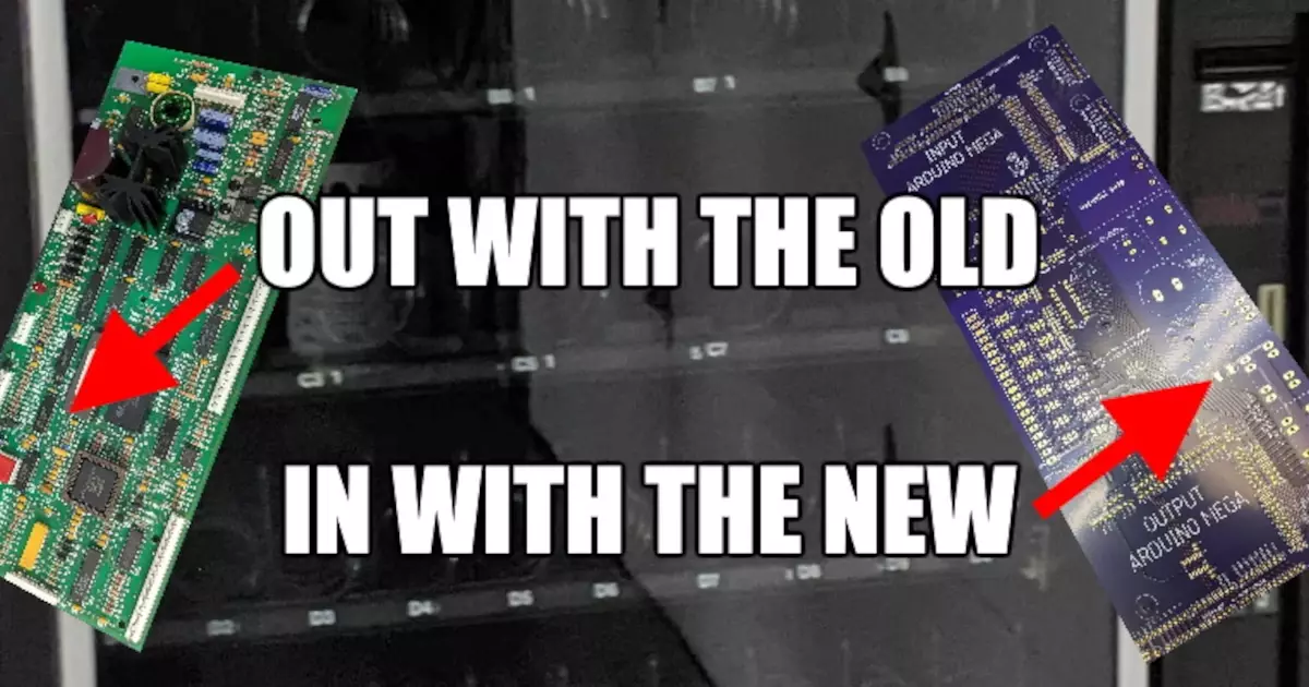
So we finished that little Python chat, which we did on Twitch, and I guess, if you want to go and and check that out, we still have that live on the Mac fat Twitch channel. But at the end of it, I was thinking, you know, I've got a little project that I started a long time ago, that this is perfect for. So I want to bang this project out and take it to the next level with that. So I've always wanted to design a an Arduino shield that has it basically a purpose built multimeter. That worked for a like a test environment. For biasing tube amps. As long as you have the right connections to the tube amps, this Arduino shield can take in all the appropriate voltages that are, you know, most of them are in the many hundreds of volts, some of them are in the like, zero to 30 millivolt range. And then it can via whatever you do on the computer, you can inform the user on where you're at, or if things are in the green or in the red kind of thing. So in the last few weeks, I banged out a schematic and a board for this, like, I don't know, this purpose built multimedia thing. So I've got, I'm showing this off to the Twitch stream right here, but we'll have some pictures of it. Got it all built up yesterday, and threw it on my Arduino. And so far everything's working pretty good. Nothing really to complain about. And this is, this is actually one of those situations where so I don't I don't code a whole lot. I even done with embedded stuff. I do some for work. But most of the coding I do for work is like initial bring up validation of functions. And then I hand it off to the really talented coders who can make it work in time and things like that. So like I make sure LEDs blink, and I make sure switches come in
that kind of make sure your hardware you validate the hardware. Yeah, pretty much
I validate the hardware. And then yeah, they make it nice for the user kind of thing. So for the most part, I'm not writing libraries, I'm writing like very specific code that just tests my hardware kind of thing. So this is one of those rare situations where I found a GitHub where somebody had a library written for these eight a D converters that I have on this. I downloaded the library, plugged it in, all I had to do was go into the header file and just change which pins were connected to the chip select line and everything function like it's just pull up whatever function was there. Like that's super rare. I feel like that never happens. Where like you just get that lucky. I mean, it's Arduino. So like that's sort of the purpose, right? Like is for those things to be more universal, but like it's just been my experience that either somebody didn't write something properly or timing is off or whatever and not this time around. So it gets it's good, kind of fun when you actually like build something You load code into it and validate it in a matter of hours. And you're like, oh, like, I was expecting this to be a lot more painful,
you'd have to spend a day and a half just tearing your hair out.
Write my code works. Why? So yeah, the Okay, so on this board, I've got two of the Gosh, ATS 1256 ATD converters, which they're 24 bit A to D converters with an eight input mux on them. So I have, effectively 16 channels have 24 bit add on this. And I'm using for teen. Yeah, I'm using 14 of those 16. And in general, I sort of made this a little bit generic, such that you can plug this into different variations of amps, and it will still like reconfigure properly. So at any one point in time, you're not using all 14 Of those, but you probably use anywhere between six and 14. And then in addition to that, I created a constant current source with with some op amps that spits out one milliamp, and then you can you can put probes to that and read voltage across it and then be able to read resistance on it, because there's a handful of resistors that their value matters in the amp. So the the kind of concept here is that you, you start by reading these resistors in the amp, get those value, store them somewhere, plug the whole thing in via a ribbon cable into a special test connector in the app, and then run a kind of a routine that then goes and just grabs everything and calculates power dissipation based off of those resistance values that you had previously measured. So yeah, kind of purpose built. But I don't know, it's been been pretty good. So far.
Some of the best test hardware is purpose built. Yeah,
yeah, exactly. Well, and the reason why you can go fast like this and get something in a week that just works is because it's purpose built, because there's so much gray area where you just like I don't care. Like I know, the resistance range that I need to measure is between 100, ohms and 2.2k. I don't need to read anything outside of that. So that's why I chose one milliamp because then I get a voltage that I have to read That's point one to 2.2 volts. That's it,
it same thing with the voltage input. So you have a specific range for all your inputs. Yeah.
And actually, it's it ended up working out that with this. So I've got giant resistor dividers on the on the front end, because I'm doing high voltage input, and I wanted really high precision, high voltage division. So these are all each one of these resistors on here, I have 10 of them. They're a 1/1000 ratio. So one, zero volts to 1000 volts is zero to one volt at my A to D and then my A to D has gain. So I can bump that up by a factor of two or four to get zero to two or zero to four volts. Although I have been testing this with no gain just going zero to one volt, and the resolution I'm getting is far more than needed. That's good. Yeah. So you know, that was that was sort of one of the big things is that USB power, which I opted to bite the bullet and make it just try everything over USB power. So this whole thing everything on this is being powered by whatever you plug this this into over USB and I was a little bit crossing my fingers on that because USB power is usually garbage, right? Like the spec on it is not particularly tight. And the noise level is can be all over the place. Right? I mean, technically, the noise can be enormous. And and actually I'm seeing a bunch of noise on this. I don't think Arduinos are like specifically known for having very low analog noise, right? Like, that's not like their point. So I kind of rolled the dice on that because I'm I'm these eight ADIZ are technically 24 bit I don't need a full 24 bit resolution 17 Is what you needed. 17 was what like kind of like the bare minimum. I shouldn't even say that. Like, I don't even I could probably get away with 12 bits and still be like plenty reasonable because at the end of the day, what am I calibrating I'm calibrating an old like vacuum tube amp where the tolerances for everything is like 20% So anything above a handful of bits and I'm already past that, but this was more Have a challenge to myself, I wanted to be able to resolve 10 millivolts on a 500 volt signal. And I haven't done an enormous amount of testing, I've only had this built for less than 24 hours here, but I'm already getting something in that range. The biggest thing I need to do is test this with better test equipment. Because as Parker and I have talked multiple times in the past, we both have Harbor Freight meters. And there's no way that they're counting up to that level.
So we have used in our personal lives, it's used equipment and bargain bin stuff,
right? I have a better meter that's integrated into my scope. But it's still not good enough. So I'm actually going to do some measurements with some equipment I had at work. That'll be that'll give me a little bit better. So regardless, the the what's nice is I was I was really concerned about the noise because I use a, I used a dc dc switcher on this. And it's it, maybe my layouts not phenomenal, I did opt for a full ground pour across the entire thing, as opposed to doing separate analog digital grounds. The reason I did that is just because like, this all connects to an Arduino at the end of the day. So like, Okay, I don't want to get fancy with it, because it's already kind of screwed to begin with. Yep. So I just like make it easy, just do a solid ground floor.
So my question is, yeah, when you hook up a high voltage line and the ground for the high voltage line, are is the USB coupled to that ground?
Yes, it is. Yeah, I know. i It's risky. It's risky, right? The the solution to that is perhaps using a laptop.
Actually, I solved this problem at work. You can buy on Amazon, as you can probably buy anywhere. This is where I bought it. I bought a you an actual USB isolator that plugs in in, in series with your USB cable, and it does work.
Does it? Can you deliver power over it?
Ah, yeah,
I think so. Okay, because I need 100 milliamps of power. Yeah, that's it can do that. Okay. And that might be the solution. Right? That might be the end of the day, if so far, I haven't had any issues with that. But also, well, but also so far, I haven't plugged it into an amp yet I've plugged it into, but I have coupled its ground to a high voltage power supply. So I do have this thing grounded through the USB cable through a laptop, but also to mains ground through other gear. And it wasn't noisy. So
yeah. I was using a piece of test equipment that's doing FSK modulation for Highveld voltage FSK modulation. And it's in, I kept basically exploding, like USB hubs that were connected to it. It refined for a couple of days, this is the thing, it's fine for a couple days. And then one of the devices under test is actually a bad D bad a bad unit that causes a voltage spike on that USB line coupled with the hub and thankfully, it just usually just takes out the hub. But I've had it taken out of a multimeter before too. And I got a I basically I finally managed to get enough time to look at the schematic and I'm like, Oh, the high voltage line on that. For this. This FSK modulator is coupled, it's actually it's really funky because the high voltage positive line is connected to the ground of the board. It's using the negative line to or the the ground for the power supply to actually do the level shifting really funky. And so basically, when you turn on that power supply, it's shifting the entire ground have the USB to like make it a 300 volts.
Oh, okay, well, yeah, that's yeah, that's not gonna do
so much. It's fine for a little bit until whatever diodes are not happy in that USB hub. Right, basically go out. But they're not putting an isolator that solved that problem. So it will probably you don't have a problem yet. But if you might,
I might run into it. I don't have that kind of situation. This this device will be plugged into the app before you turn the amp on. So when you first turn the amp on there will be a large current draw, but that should be isolated entirely inside the amp that should not draw through The USB, correct Yeah. And so I've got it written on the, on the silkscreen, the high voltage areas only here and the high voltage only touches the voltage dividers, there's no high voltage anywhere else. So from basically this point down the highest voltage you can get as five volts. So I don't necessarily have the same kind of problem, but I might, I may just get the isolator just to be safe.
It's a safety thing. Right, right. This is this. You just got a new laptop.
Yeah, well, and I tested this on some bad lap hubs. I did not put this right into my new laptop. Just from the get go. So yeah. Yeah, yeah. So luckily, everything even though there's there's a bit of noise due to the switcher, it's not actually raising the noise floor too much, that when I do enough measurements and do my averaging that I need to actually pull off, I can get five zeros in in a voltage measurement so I can get down to microbial reading, which is way thumbs up. That's a That's an order of magnitude greater than what I needed.
You using your voltage standard power supply, right. The Missouri
not yet actually. So I want to, but about a year ago, I pulled that thing out, and I turned it on and it shorted. Oh, I know.
I know. It's part of the caps actually. Because remember, we pulled that thing apart once and the caps were looking a little suspect. And I think we ended up just not replacing them. It still worked. It worked in a calibrated Awesome. Yeah, it was still working. But like we opened it up in some of the capsule, we're looking at the little suspects. So I bet you're one of those finally went and
well, what's nice about that board is or that whole unit is it has a its power supply. And its main like function boards are entirely separate. So I can disconnect them and just test the power supply and see if the fault exists there. Because when we fixed it, all we had to fix was the power supply last time, so I'm kind of crossing my fingers. But if you remember I had to buy like a really unique voltage regulator off of eBay, because it doesn't exist anymore. And
I don't know what we should or shouldn't replace the couch.
Probably should have. Yeah. So it's popping fuses, which is that's annoying, right?
Yeah. A bunch of some of those caps are a little little leaky.
Yeah, it. I'm just afraid it's more than that. Because if it's more than that, that thing is a paperweight. Right?
I well then get rid of it and get it out of your garage. Probably
that's probably the best. I mean, for now, what I'm going to do is just verify this thing against a good fluke. That's, that's my next is the
one that that's written on the back NIST certified on the back, you bet or NIST traced and this
certified at some time. Date? No, it doesn't. No, no, it does actually have a calibration sticker. It's just, it was written in Sharpie on there. That's
my favorite, but it doesn't have like a date or anything though. It's just as calibrated and Sharpie as better than the most places though better than most places don't. Don't have anything calibrated
under the little flappy wing, the little kickstand on the back. There's an official Miss calibration sticker with a date. That's out of calibration. Let's see here. Oh, okay. So yeah, the resistive measurement. The other portion of that, like I said, I built a little op amp circuit that just cranks out one milliamp. And I tested that on one of my meters here, and I was getting 1.001 milliamps. And the thing is, I used nothing but point 1% resistors in that whole circuit, and then I used actually a bunch of them in parallel to kind of get, do our old trick of getting better tolerance by using in parallel. So I actually kind of believe that that 1.001 milliamps, I'm going to verify that once again on better equipment, but it seems about right. And then I put a 1k resistor and I measured voltage on it and it was really close to one volt. So go figure it seems about right. Yeah. The interesting thing is the actual values I'm reading for the voltage. On this bias test system, all of the volt voltage reading seem to be good. They're all like within range, I swept my high voltage power supply from zero to 300 volts. And I tested that against two other meters while reading on this thing, and this thing was within 1% of both of my meters, so that doesn't mean that it's spot on. That just means means that it's tracking the way that my meters do. Right? So like I, I'm starting to trust this.
And honestly, I bet you what you built is probably better than those meters.
Oh, yeah, no, I'm actually I would bet this is yeah, for sure. Which is funny. Yeah. How do you test something when you are the one who built the better thing?
It's, um, it's actually a very good question. We need to have like a test, a test equipment engineer that, like designs that stuff on this podcast to talk about that,
you know, okay, so I was actually looking at getting somebody on a little while ago, just actually, last week, I was looking into it, I'm looking for a metrologist. I want to get a metrologist to come on and talk about the science of measuring things. And like, how do you measure things? And then how are you confident in your measurement? And what how are we all screwing up measurements? Because I know we are right. So I think I think that would be really fun. Because you know, I'm doing this project right now. And Parker and I have talked about a bigger, more grand multimeter project. Well, having someone come on and talk to us about like, how you actually get validate that, that I think that would be fantastic. So if anyone knows a metrologist that would be willing to talk to us. Even if it's a metrologist that deals in measurements of like, not electronics, but like physical things, I would still love to talk to him.
Because the science still applies, right? It's actually a very interesting thing is like, it's easy to design something when you have a design something that measures something when you have stuff that's better than it, to calibrate it to
write. Well, and that's why Parker brought up my voltage standard, because the voltage standard I have is way better than what I just designed. And it was calibrated by a thing that is that we know is better than it. So like I should have been able to pass it down the line. Yeah, it was.
It was that it was that Keith Lee? Was it Keithley? Yeah, yeah. Is it? Keithley? Like seven and a half digit. multimeter
Oh, yeah, we were measuring down to nano volts. Yeah,
I would think it was a lot of fun. Actually, at that point, we
were probably measuring incorrectly somehow, like, when you get down there, like it's everything, all bets are off, right? Unless you're perfectly right. So the the interesting thing, okay, so yeah, the all the channels seem to be reading voltage, great. The resistance measurement has an error in it. And I don't, I haven't figured out why yet. I've identified the error, but I don't know what's causing it. It, the error seems to be about 1.7%, low for any resistor, I plug into it. And like that number is that 1.7% is like, it's perfect. If I put 100 Ohm in there, or a 1.5k or whatever, it's always that low. So there's like a gain error somewhere. And and it's interesting, because I can have the resistor on the board, I can measure the voltage across the resistor with a with a meter and the voltage is right on the meter, and I get a low reading on the Add. I'm not entirely sure what's causing that right now. Because all the other measurements are proper. So I don't know, I gotta gotta dig into that one. I don't necessarily want to start, like making offset corrections in my code, just because an error exist, I'd rather figure out why the error exists, you know?
Yeah, it could just be, you know, the offsets just in there, though. It's part of the intrinsic value that ADC.
It could be, but all the other ADC channels are functioning fine. It's just that one. Oh, yeah.
And I guess you need go into datasheet for the ADC and see what the offset of the Muxes basically can be.
Yeah, yeah. But like I said, it's a it's a percentage. So it changes based off of the voltage that's in. So that's why it seems like a gain error somewhere. So I don't know, I still need to play with it. Like I said, I've just identified that it exists, I haven't identified all the ways that it exists. I just put different values in and realize that like they were always low by a very particular amount that is consistent regardless of what resistor you put in and only on one channel, only on that channel. So yeah, it's strange and like I said, I validated the the constant current is spitting out what it should be. And on a meter across, you know, if you have one milliamp through one kg of resistance, you should have one volt across that resistor. I can validate one milliamp and one volt on a meter at the exact same time that the ADC is read. In less than one volt. So yeah, it seems intrinsic to the ADC somehow.
But it's only that one channel. So I wonder if that one channel? If it was a gain value, I would assume that that that ADC only has one gain stage. It does. And so the MUX is before basically the the gain stage, that's exactly it. Yeah. Yeah, it's gonna be the MCSA and MCSE, inside there might have a might does have a offset, and just that's on the worst case of it.
It might also be loaded. Weird. That could be something that's that's causing issues, because all the other channels are a low impedance, op amp that are driving all the other inputs. Whereas this one is reading directly across a low impedance resistance.
Oh, that's exactly what it is, actually. So
that's what I've been fearing. And so I've been around, I wish I would have put a buffer in between there. But the reason I didn't is because I had used up all my offensive channels. So I was like, well, we'll, we'll go with that. So I'm, I'm thinking it's that
it's probably drawing a bit more current than the other ones off that ABC.
Right. So Oh, playing around that. And if that if that is the case, like I said, I it's a it's a it's a specific amount. So it's, I can just multiply my my value and, and get the answer. So it's not the end of the world. And I'm already way more accurate than I need to be. So any errors that show up due to multiplication, I think would be still within the realm of reasonable numbers. The cool thing is, so I use some some op amps that I've been using at work and I found these offensive. I talked about them, gosh, months ago, on the on the on the podcast, they are the TL V. Let's see here. I haven't written here TLV that TI?
Yes, they are. But they're like, they're generic replacement, Jelly Bean op amps. But they're like, too good to be Jelly Bean op amps.
That's exactly right. Yeah. And they're, they're also new. So they're going to be in, in production for a good long while. They have, gosh, well, I don't I don't remember the number to V, you know, I have my schematic up, let me not TLV 9154. So this quad package has really, really low current consumption. But one of the things that's really nice about it's a really low offset, the typical offset from each amp is 125 micro volts. And typical is 125 maximum is 750 micro volts. So they're their sub one millivolt offset, which, if I didn't calibrate for one millivolt worth of offset, that would mean an error of one volt on my total output. So if we're thinking about I'm trying to measure 500 volts, and my guaranteed error is within one millivolt. Like I'm still like way, way low on my measurements. But I think I can calibrate all that out. Because what's cool is, is if you cycle through the channels and read this, I can actually very easily see this offset, because I'm reading down to one microvolt, I can easily see the offset of each one of these op amps. And the nice thing is, the noise is actually low enough that I've been able to average the snot out of it, find out what that offset is and then calibrated out. And that's how I can get down to one microvolt.
So you're already doing offsets and stuff in your code.
Well, but it's a measurable and an unknown offset. Thing is again, like it that's just a fixed offset. It's always there. Gotcha. Gotcha. Okay, I
see what you're saying now. Yeah,
well, and that's sort of one of the one of the things I want to have in the test GUI is I want it such that when you when you load up, there's a button that's like a, like a zero button where it'll go channel by channel, and then make sure all those offsets are taken out and you start fresh from zero. You know, other than that I'm getting, I'm getting down to one microvolt. Now, let me let me make sure that I clarify by saying I don't 100% know, I'm down to one microvolt it's just these ADCs are reporting one microvolt worth of worth of change. So I have to validate that and that's actually going to be pretty tough, but that's where I said earlier, I can get to five zeros on my on my input values kind of thing, which one microvolt of change equates to one millivolt of voltage in the amp. And my target goal was being able to read 10 millivolts so I'm about one order of magnitude better than what I'm hoping for, and in all reality it probably We'll be once everything gets put into place. And you know, I've got cables and stuff floating around now, it'll probably get more noisy. And I'll probably get closer to 10 millivolts, where the resolution on a 500 volt signal, which is exactly where I wanted to be. So, yeah, I'm pretty happy with it. So far, everything kind of kind of turned out well, sort of next steps with this is to finish validating everything. And then I've got to merge the, my two sketches because I've got the Skippy sketch. And I've got my sketch that's doing all the reading, I need to figure out all the things I want the Arduino to do, because really, I'm thinking all that I've really wanted to do is just cycle through all its measurements and throw it in a mailbox. And that's the entirety of what the sketch does. And then Python just says, Give me, you know, the contents of this mailbox. And that's totally do that. Because I think that's the easiest as opposed to having Python talk to the Arduino, then the Arduino goes and does it. I'd rather the Arduino just be running its own thread that's just nonstop. Yeah,
you can do it that way. Yeah. And that's how that's how the buttons work on one of my fixtures that work is the Arduino side, is just pulling the switches and sticking it into the result in the mailbox. And then on the computer side, the computer goes, What's the value of the buttons, and the Arduino just spits out with the mailboxes and then clears the mailbox out. So you probably don't have to clear the mailbox out
for your I'm just gonna just, it'll just open the mailbox. If there's something in there, it just burns it and then throws the new value in. And then Python we should do when Python grabs the value. It doesn't need to erase the value from their mailbox. It just looks at it.
Yeah, yeah.
I kind of liked that better when they're disconnected.
Yeah, well, you have to so your computer, and Python is asynchronous, right? So you have to treat that communication between the two is asynchronous? Well, I mean,
you don't have to I mean, the other solution is kind of what I said, Where Python could make a request to the Arduino. And then the Arduino goes and does the does it and then brings it back. And that makes it non async. That makes it synchronous. And that seems like a headache.
You can do that. So that's how most Skippy DMMs work. Sure, usually go, you sit. So you set up the multimeter with the right config, func function stuff, and then you go sample once, and then the DMM will sample once and then you go read and to get that value back.
Yeah, that's sort of the beauty of Heaven. The purpose built multimeter, though, because all of that setup is hard coded on mine. And the way that you change the hard coded portion is just depending on what it plugs into, it'll it'll either utilize pins, or it won't. So I could get a little bit more fancy. But like, the way I'm thinking about it is you have in the GUI, you have a drop down list, and the product name is in that drop down list. So if you select this product, then it knows not to read channel three and six or whatever, you know. So you don't have to do all of those hardware configs. You just the software just ignores things. Cool. So and then yeah, after that. Parker now you're going to schedule up? Well, I guess working on a GUI and working on the next step with Python.
Yeah, we'll probably just do like a GUI explanation and not have to worry about Skippy. Sure. Because basically, you would want to do like, what I used to Kinter because it's a portable GUI interface for Python. And then because you probably need a drop down that just does that changes what functions get run basically on in your behind the scenes. Yep. And then and then some values that spit out into like, fields or something, or figured out as we go, like we did last time.
Have you've done automatic printing, right with Python? Yeah. What what what would be cool is to just build a small amount of functionality like the like the the skeleton structure in there, such that once once something is biased, like the operator can say, hey, like, this is complete, and then it prints a sticker and says, you know,
so I've only done that with Zebra printers. So you need to get a Zebra printer.
Well, I'm thinking more towards the future. Not now like,
oh, yeah, for sure.
That's why I'm saying like maybe just like the baseline skeleton. Yeah,
we can totally do that. Yeah. We can actually do it all the way to the point where like it prints it, like generates a Z PL that you need. Yeah. And then like that's it and be like, the next portion is like the plug printer in.
Oh, yeah, that'd be cool. I did that.
We don't we won't have to do that for the next one. But definitely, in the future for sure.
Right. So yeah, once I have this all validated, I've got to actually build a small little board, I'm gonna just gonna make a little piece of perf board and just Cluj in a cable into one of my amps. And just basically hard solder all the wires into an amp so I can so we can actually test this, but I'm liking it because the the amps that I have available right now, they're all they'll all take this to the extreme. They're all 500 plus volt, guys, and they like all the voltages are the top end of everything I want to do in these ones. That's good. The other thing that I gotta watch out for is these ribbon cables are rated for 300 volts, these 16 pin ribbon cables, so I got to figure out a solution to that. And the solution is find a higher rated ribbon cable or, or test it and see if it works, right.
You're using I have a safety factor of two, right? Yeah, right. Do not take my advice,
especially in high voltage land. Well, and that's just the thing, most of the conductors that are actually connected in, they're all going to be close to 500 volts. So the voltage difference is only going to be a few volts. So that as long as the cable isn't close to something conductive, then it's always getting close to the same inch the connector somehow however, there are two ground leads that go through there. So that's that was unavoidable.
I wonder what if the limit is the IDC connector connection? Or is the installation?
Honestly, I think it's actually probably the little fingers that that stab into it. And that's the IDC Yeah, yeah. I think their spacing might not be amazing.
Yeah. might have a little arcane action.
Well, we'll see. I have seen ribbon cables that are rated to high voltage, like 1000 volt kind of stuff. It's just they were, I haven't found any that I can purchase.
Yeah. Well, if that's true, that's probably the IDC connector, and it's fine. It's probably the installation then.
Yeah, well, we'll find out. I can honestly hook this up to my high voltage power supply and just juice it and see what happens. You know,
fireworks in your basement? Wouldn't be the first
time Nope. So real quick.
Next subject.
I've kind of been posting about this in the Slack channel. And I don't want to dog this too hard. This actually opens up a question that I want to ask you, Parker. Just get your thoughts on it. So this section I've called it gripes about Arduino. Arduino is fantastic and amazing until you start to try to design physically around the Arduino. The the website the Arduino website has has okay documentation in terms of you can download the schematic schematic the PCB file, they have dimensional drawings and things like that. But, but there's some unfortunately, there's some unfortunate design decisions that happened with the with the Arduino that make it a little bit of a pain to mechanically design around because in the time I was waiting for the PC board for this I was wanting to design up a little enclosure. And since I have a nice CNC at work, I can just you know program in holes and go and cut it and I realized that that's not as easy when you look at the Arduino. So a lot of our Slack members probably have already seen it but I was complaining about some of the mounting holes that are on on an Arduino. They're the the hole size was chosen to be 3.2 millimeters. So that just screams like a free fit for an M three. Screw which Hey, great, like M three is available all over the place and it's easy to get. But I don't think they took the head of the screw into account because an M three will fit through the hole. But you ain't gonna get the head near any of these. Like they put stuff like butt butt up right to the edge of the hole. Yeah,
I mean, here I have an Adreno mega right here. There's a hole right there.
Yeah, it's like he showed me a hole that is like touching two adjacent pin headers.
Let me measure so that I actually have my calipers right here. I'm gonna make sure that the spacing is let's put it in metric because it's probably metric spacing. is five millimeters between those two?
And an M three? Head is six.
Yeah, so you can get a m three screw in there.
Right? And I doubt you could get a 440 in there without some adjustment.
No, you wouldn't be able to. So yes, I do you agree that's the biggest. There's two big things with Arduinos is one, the mounting holes are terribly designed the locations and what's around them, because like one is near like the DC jack. So if you had like a conductive nut, like fastener, it's going to short there. The solution to that is to use those Praesent style that a PCB mount pressing that like nylon, so you just snap the board in.
And you know what, we might be dogging them that might have been the original design could be Choisy, which does totally fine.
Are they actually the right size for that? I don't know what, let's see. Well, okay, so
there is one kind,
they are not the right size. So those are for the press and style, at least the ones that I've worked with those are they require 156 mil hole.
That's almost four millimeters.
Yeah, these are 128 mils. So what is what is 156? In metric? A 156 is six millimeters. six millimeters.
Look at look at two Americans trying to match it's actually four millimeters. four millimeters. Yeah. Okay, I had it right before. Yeah.
So the holes aren't big enough for the presents, unless there's unless there's smaller pressing styles that I don't know about. The only ones I know of are four millimeter or 156 holes, so that wouldn't work.
Well, okay, so the Arduino came up with a solution to this. And this, I wasn't aware of this, but it's it ships with all Arduinos. Now, I haven't bought an Arduino until recently, last time was years ago. There's a little plastic sled that comes with it now. So the Arduino fits nicely inside this little plastic. That's the best I think I can say is the sled. And it has mounting holes that are kind of in a little wing that hangs outside of the device. Now it's only because only two of them. Two of the mounting holes are there because two of the mounting holes at the back of the Arduino can actually accept an M three screw with a proper six millimeter head. So that was there solution.
You know, I wonder what we did at Dynamic perception because we use Arduino. Who knows? Basically, it was the previous version, which was do we mauve? vano? Something like something like that? Yeah. We use those, those Arduinos. And they were mounted into that chassis, or that enclosure? I don't remember how and I don't think I have. No, I might have some at work. Or I'll ask Chris church. If he remembers how they were screwed in, because I think they're screwed with four screws. Couldn't be the same mounting hole pattern, as you know does.
Well, perhaps you used smaller screws and offset them sets that the head would actually
fit. I think we used pan head screw nut pan head leaded flathead. So the angle kept the head off the board basically. kind of funky.
Yeah. You know, that could work. Right?
It worked and not the sell several 1000 of those things. Right? Right. Right.
Well, okay, so then there's one other thing and this is actually a lot less of a great for me, but I can I can understand other people being annoyed with this. But you know, the whole classic spacer, the 50 mil space, the 50 mil space, so it doesn't work with perfboard Yeah,
so that's always been a big thing about arduino big gripe. And so what the I think the official story was when they were developing it, the hardware side of it is it was a mistake. Yeah. And then it was kind of like, notice too late. And they've and people have already built shields and stuff that worked with that spacing, and so they just never changed it. Now that there's a conspiracy theory, oh, that Arduino did it big so that perfboard couldn't work with it. So you had to buy the Arduino shield perfboard stuff. You had to buy their accessories. I don't really believe that too much. You don't buy that at all. I think it was just truly a mistake and it was just noticed too late to kind of back out. They probably built a whole bunch of children's lines and stuff and then started manufacturing stuff and didn't realize until like, maybe like after they got a whole bunch of PCBs made that oh, that's probably not a good idea. Oh, well.
Well, and check this out. They have custom headers now. Yeah, like the headers for a while. But
yeah, they have custom headers that have a 50 mil space. Yeah, instead, well, it's actually 150 mil. So it's like 100 mil 100 mil? 100 mil 150 100 100 100 100. Which Oh, yeah, so they got custom injection molded, basically pin headers, but they're really nice, because they have like, the signals are printed on
them and stuff. This signals are printed on both sides of that. Yeah, they're really nice. They're super nice. Now, like, like I said earlier, like, this doesn't bother me too much, because it's a shield design, I'm not gonna make a port forward, I'm gonna go out and make a custom PCB. So and like, it accepts pin headers, like, it's super easy. Like, they didn't make it such that I had to get a custom part. But I could understand somebody wanting to prototype something with a with a perfboard. And being like, really? And then, you know, I don't know having a cut a perfboard, jumper over or whatever. So that seemed like a design mistake. And
perhaps I think there's an oversight. Right? That went too far.
Yeah, you're right. Your mistake might be a little harsh. Their oversight, oversight is probably a better, better word. And this is a question that I would like to ask you, Parker. And maybe this is actually a good question to extend to our Slack team to kind of get out there, or you call them a team now? Oh, yeah. Yeah. Our 600 strong team. When do you bite the bullet and fix a problem? Is is the question. And what I mean by that is like, Arduino. When should Arduino bite the bullet and fix this? Or should they bite the bullet? And so
this, they will never go? They're never going to fix it. They've already said they're never going to fix it. Sure. So there's interest. Interesting thing about this question is, it depends? It depends on if you're if you are okay. With the monitor. So there's two things with this. There's the monetary, and then there's the moral. Okay, you know why? Because sometimes the monetary dictate dictates one path. That is don't fix the problem. Because monetarily, it makes sense. But morally, you should fix the problem. Because you might be Ford and have a Pinto that explodes when you get your car rear ended. But it's cheaper to keep the problem broken, and just pay out lawsuits. Right? So it depends. Yeah, everyone in chat is just putting like dollar signs. So it's dollar signs, unless there is a ethics problem with keeping it with that decision.
Well, but but but okay, this these kinds of issues they knew from way early on. So they could have been asking them themselves this exact same question the entire time. So I don't believe it was always a money thing.
I think, no, I think it will, I think originally was a money thing, is they built a whole bunch of boards and a whole bunch of SHIELD designs, then notice that it was too late. And then we'll be like, well, we got to sell how many they made their first run, I don't remember or no. And then once I got out in the into the free world, people like people design shields for that pins. And then once you know, that happens, then just they made a standard bait by accident. Right? Yeah, they can't change that standard.
I don't I don't agree with the can't change that.
Well, they can. But then everything. thing is it's fine. It's great. You ain't screwing back compatibility. Yes. Yeah. You're messing up backwards compatibility because even the mega which came later has that same issue. So that's the thing is, I don't think yes. It's one of those. They'll probably never fix it because it doesn't actually hurt. It's not there's no ethics or reason for them to fix it.
The pin spacing, I don't think really hurts much. The mounting hole issue, I think has more of an impact. Now, that brings up a lot of questions about should you be needing, like, if you need to mount an Arduino into something, you can probably find a way right?
Yeah. But you know what I always do double sided sticky foam.
I mean, I might, I might do that. But like that's annoying, right? Actually, yeah, I've seen I've seen more than one test rack with double sided tape, or two
subs. Awesome.
I gotta be nicer.
I have to I've two kinds of sticky foam that this is what every engineer should have in their drawer should have the, the super thick. It's kind of like a Manila white color foam. Yeah, that's really squishy. It's kind of got like a low tack to it. But then your student had the VHB style from 30 M, which is like dark gray. And it's thinner. But that stuff. They build like cars with that stuff. Oh, yeah. And on VHB Tape, if you if you actually want that stuff to be permanent, you get VHB primer. And it's like, it's almost like an alcohol. So you clean the surfaces, like with alcohol wipes, and then you put this primer on it, and it dries really quick. That VHB tape would never come off. You will permanently bond things together with a VHB Tape. If the best thing is What does What does VHB stand
for? Very high bond. Yes, exactly. Was it that was a guess.
Three, three M is really good at naming things. Yeah. Forever. What is three M stands for a bunch of something similar.
Maybe I don't know. The maddening whole thing kind of kind of bugs me about this Arduino stuff because it was designing a
SOTA mining and manufacturing company three.
Okay. But okay, so if I'm designing an enclosure that's supposed to work with like, actual hardware that you can actually design around and actually measure. Now now I have to come up with a tape solution, or, or like goofy little click on Standard, what
you should just do is just make an own one board that has your built in isolation.
I thought about doing that of just like putting an Arduino on a board on this board with with the rest of my stuff. I even have space for it. I could have done it. Yeah. But I was I'll make faster,
you know, yeah. But that's always Reb to
I don't want to rip to it because it works doesn't work. It works
like and you are adding in more complexity that can end up mate causing a rev three to happen. Also, this
was $170 worth of resistors. Like, no, I
don't want that unsought or they're putting on a new board.
I honestly, I would, yeah, I really would. It's interesting at Mauser these, these resistors. The it was the exact same cost for nine of them, and was the same cost as 10. So it's just sometimes the price breaks work out where it's just like buy more.
Yeah, I think DigiKey has that has that thing where it will let you know that the next price break is a better deal for you. Oh, that's cool. Yeah. I don't know if they're still doing that. I'm pretty sure that was a thing at one point. though. I swipe up this with one last topic. Yep. Supply chain, oddities that I've been kind of supply chain is all messed up. We're not going to talk about that, because everyone knows that. We talked about it a lot. So I'm sorry, I'm working on my new design. It's actually an old as old project from a long time ago. Not going to go into that either, because it's not 50% done yet. But I was noticing that I can get pretty much any linear tech device I see out there. Like I use everything in my design. I'm actually like doing a lot of linear tech ICS for it. Specifically like the LT 8672 which is a rectifier, controller for input input, protection, input voltage and Spike protection. But what's interesting is analog devices, Analog Devices devices are really hard to find right now like you are like sold out everywhere. But Analog Devices owns linear tech. And I wonder if this comes down to where a lot of people do not design with linear tech devices because of that whole like, you might find the perfect chip with LT but to have like eight in stock ever And also, you know, slightly more expensive than competitors. But they, man, linear Texas got some awesome ICs, which is why I'm going with them for this, because only need built one really. But I'm basically a long time ago, I say a long time ago, sometime this year, I found that linear Tech Automotive power supply design white paper. And so I'm actually implementing that because I kind of want to build it and test it and see how that works.
Are you able to give us just a hint on what it is?
It's the the Jeep problem. Okay. Yeah. And I'm actually using the prop one still, because like, I already have, I already have all the code for this thing done. Something like, I just got to reuse that my controller? Yeah, for sure. And I can get I can get, and funnily enough, the I think the parallax propeller might be the only microcontroller you can get by right now. Yeah. That's great. Probably Same reason for linear tech. It's a, you know, kind of like a weird brand, right? The funny thing with this supply chain stuff is it seems some stuff is starting to come back in like for interior, like, capacitors and resistors never had a problem with this current wave of supply chain issues. Same thing with connectors. It's mainly been ICs. Most ICS seem to be coming back in some form except microcontrollers. I wonder if the wafers is the is the bottleneck right now for microcontrollers. That's just my guess. Uninformed decision, or uninformed statement, I guess, right there Beyoglu batches wafer wafer. Certain wafers are that they use for most microcontrollers are probably hard to get right now. Because I know because I have like, the entire world supply of a specific Atmel microcontroller on my desk here. And it fits in a box. It's like this big
12 inch bucks. Yeah.
But it's like the world's supply. There's like 2000 microcontrollers in there. Yeah. So it's amazing to think about that's like, the world's supply, at least for right now. And don't worry, people don't hate me. They are going directly into products like next month.
Oh, you're not you're not just hoarding them.
No, I'm not ordering them. I need them to build stuff. Because I shipped a ship 250 predators. Nice. And so now I got to build like 1000 Plus more of them. Wow. And then ship 20,000 LED boards.
So very cool. Congratulations.
Oh, yeah. Oh, thank you, Steven. Fancy in chat. just posted a article that's microcontroller supply chain is out of control. So I don't know what that says. But it's probably probably saying something similar to what I just said.
I mean, it has been out of control. Yeah.
Guess what, we should wrap up this podcast then? Think so? Yes.
Okay, so that was the macro fab engineering podcast. We were your hosts Stephen Craig
and Parker Dolman. Take it easy. Later, everyone.
MacroFab's Misha Govshteyn and Chris Church check in with Parker and Stephen to give his take on supply chains, nearshoring and reshoring.

Part shortages and obsolescence got you down? Parker and Stephen have some tips and tricks to help your design stay ahead of the End Of Life game!
Nichicon is obsoleting entire electrolytic capacitor lines. Is this a sign of how electronic component manufacturers will handle supply crunches?