Related Topics
The EU Charges Apple Up, Down with Slack, Don’t Go Changin’
Discussion on USB-C, EU chargers, tech, Slack GUI, government regulation, tech innovation and reverse polarity.
The Name Will Arrive
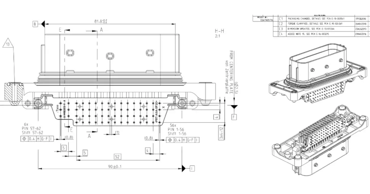
The quest for the right connector for a project! The right of passage for any hardware electrical engineer starts with a connector catalog.
Connector Catalogs
This is the last installment of Stephen's 'Adventures in Injection Molding'. We are going to recap the entire two year sage and close the book on it.
Other Resources
Circuit Break Podcast
Webinars
Videos
Tour MacroFab's ITAR-Compliant Facility
January 23, 2019, Episode #156
- Parker
- Wagon Chime Module
- Installed back on Wagon and It works!
- USB Type-C Article Update
- Have the Type-C to FT230X complete
- Design Block for Eagle
- ESD protection on the CC Pins?
- IP4234CZ6,125 USB ESD protection
- Wagon Chime Module
- Stephen
- Found the old ribbon mic from MEP EP#110: Dangling Transformers
- Going look at doing a quick spin of a stacked PCB based version instead of the 3d printed chassis
- Boards can screw together to clamp to the ribbon itself by having a gold pad on the PCB
- Need a way to do fine tune adjustments on the ribbon tension
- Embedded transformer
- 3D printed enclosure – Fusion 360 to 3d printing?
- PCM2912A
- Brian Benchoff’s Oreo Stackup PCB
- Found the old ribbon mic from MEP EP#110: Dangling Transformers
- R.F.O.
- MIDI Association Announces MIDI 2.0 Prototyping
- Will be announced at NAMM 2019 (Jan 24-27th)
- In prototyping phase
- Fully back compatible with 1.0
- Solder Surface Tension and Why You Should Care
- The Current Source aka Derek has a released a really cool video on surface tension and how it relates to PCB Assembly
- Derek was on MEP EP#103
- A Choice of Grippers Helps Dual-Arm Robot Pick Up Objects Faster Than Ever
- Dex-Net 4.0
- Multi tool picking robot
- Successfully grasp 95 percent of unseen objects at a rate of 300 per hour
- Humans do double that at near 100% success rate
- Learns how to grip things by simulation
- The physics it uses is slightly randomized to “cover up” sensor defects
- The Basics of USB Battery Charging: A Survival Guide
- Maxim app note on Lithium Battery charging over USB
- A bit dated as it only covers BC 1.1 but still applicable to USB 2.0 devices
- New Mouser interface?
- Part Searching just got more time consuming?
- MIDI Association Announces MIDI 2.0 Prototyping
Visit our Public Slack Channel and join the conversation in between episodes!

Schematic for the USB Type-C interface for USB 2.0 using a FT230X as a USB to UART bridge.

Layout for the USB Type-C interface for USB 2.0 using a FT230X as a USB to UART bridge.
About the Hosts
Parker Dillmann
Parker is an Electrical Engineer with backgrounds in Embedded System Design and Digital Signal Processing. He got his start in 2005 by hacking Nintendo consoles into portable gaming units. The following year he designed and produced an Atari 2600 video mod to allow the Atari to display a crisp, RF fuzz free picture on newer TVs. Over a thousand Atari video mods where produced by Parker from 2006 to 2011 and the mod is still made by other enthusiasts in the Atari community.
In 2006, Parker enrolled at The University of Texas at Austin as a Petroleum Engineer. After realizing electronics was his passion he switched majors in 2007 to Electrical and Computer Engineering. Following his previous background in making the Atari 2600 video mod, Parker decided to take more board layout classes and circuit design classes. Other areas of study include robotics, microcontroller theory and design, FPGA development with VHDL and Verilog, and image and signal processing with DSPs. In 2010, Parker won a Ti sponsored Launchpad programming and design contest that was held by the IEEE CS chapter at the University. Parker graduated with a BS in Electrical and Computer Engineering in the Spring of 2012.
In the Summer of 2012, Parker was hired on as an Electrical Engineer at Dynamic Perception to design and prototype new electronic products. Here, Parker learned about full product development cycles and honed his board layout skills. Seeing the difficulties in managing operations and FCC/CE compliance testing, Parker thought there had to be a better way for small electronic companies to get their product out in customer's hands.
Parker also runs the blog, longhornengineer.com, where he posts his personal projects, technical guides, and appnotes about board layout design and components.

Stephen Kraig
Stephen Kraig is a component engineer working in the aerospace industry. He has applied his electrical engineering knowledge in a variety of contexts previously, including oil and gas, contract manufacturing, audio electronic repair, and synthesizer design. A graduate of Texas A&M, Stephen has lived his adult life in the Houston, TX, and Denver, CO, areas.
Stephen has never said no to a project. From building guitar amps (starting when he was 17) to designing and building his own CNC table to fine-tuning the mineral composition of the water he uses to brew beer, he thrives on testing, experimentation, and problem-solving. Tune into the podcast to learn more about the wacky stuff Stephen gets up to.
Special thanks to whixr over at Tymkrs for the intro and outro!
Related Podcasts

This Podcast Intentionally Left Blank
Mandatory USB Type-C for everything? Parker and Stephen discuss the current EU ruling and preparing your PCBA design for contract manufacturing!
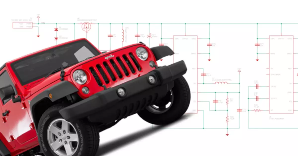
AVRDUDE All The Way Down
The Jeep Prop Fan project rides again! Well some iteration of it at least. Lets design an open source PCM (Power Control Module) for automotive apps!
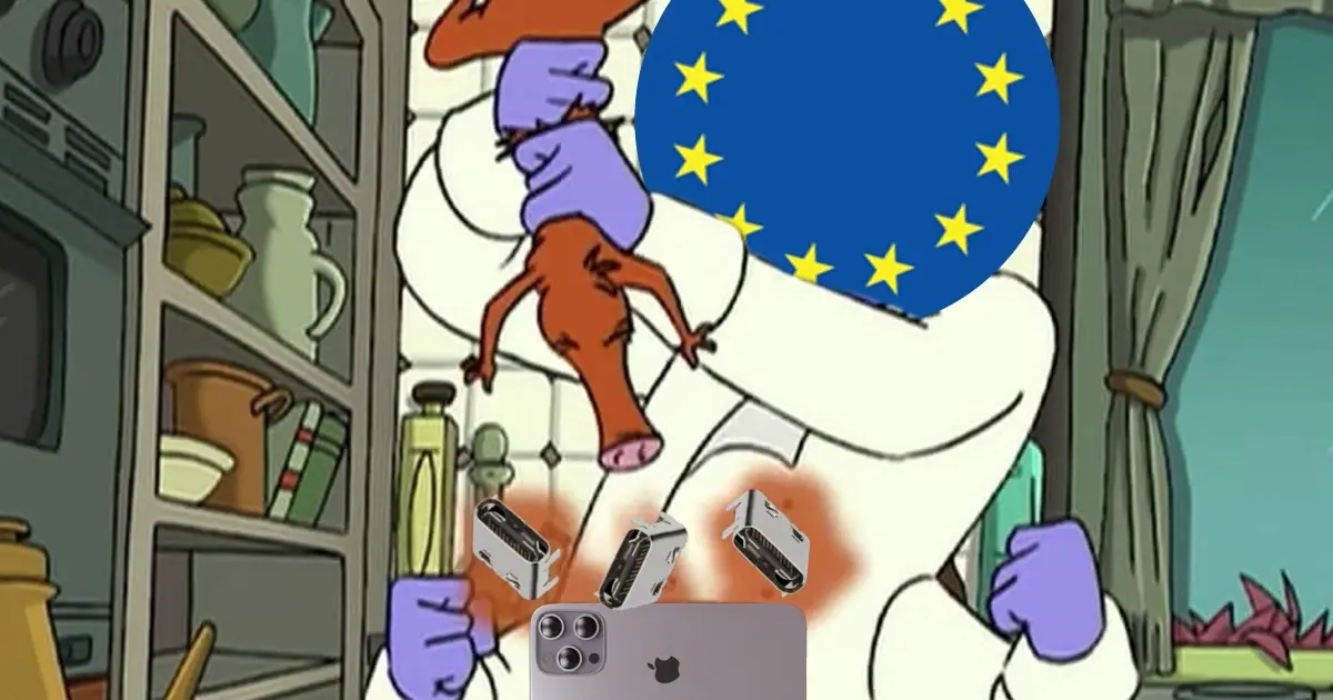
The EU Charges Apple Up, Down with Slack, Don’t Go Changin’
Discussion on USB-C, EU chargers, tech, Slack GUI, government regulation, tech innovation and reverse polarity.
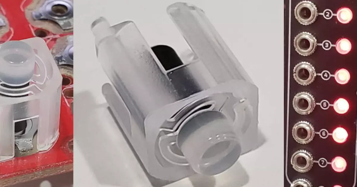
Connector Catalogs
This is the last installment of Stephen's 'Adventures in Injection Molding'. We are going to recap the entire two year sage and close the book on it.
The Name Will Arrive
The quest for the right connector for a project! The right of passage for any hardware electrical engineer starts with a connector catalog.
Illuminati Moment
Is there a statue of limitations on open source hardware projects? This week, Stephen and Parker dive into what open source means for both of them.
About MacroFab
MacroFab offers comprehensive manufacturing solutions, from your smallest prototyping orders to your largest production needs. Our factory network locations are strategically located across North America, ensuring that we have the flexibility to provide capacity when and where you need it most.
Experience the future of EMS manufacturing with our state-of-the-art technology platform and cutting-edge digital supply chain solutions. At MacroFab, we ensure that your electronics are produced faster, more efficiently, and with fewer logistic problems than ever before.
Take advantage of AI-enabled sourcing opportunities and employ expert teams who are connected through a user-friendly technology platform. Discover how streamlined electronics manufacturing can benefit your business by contacting us today.