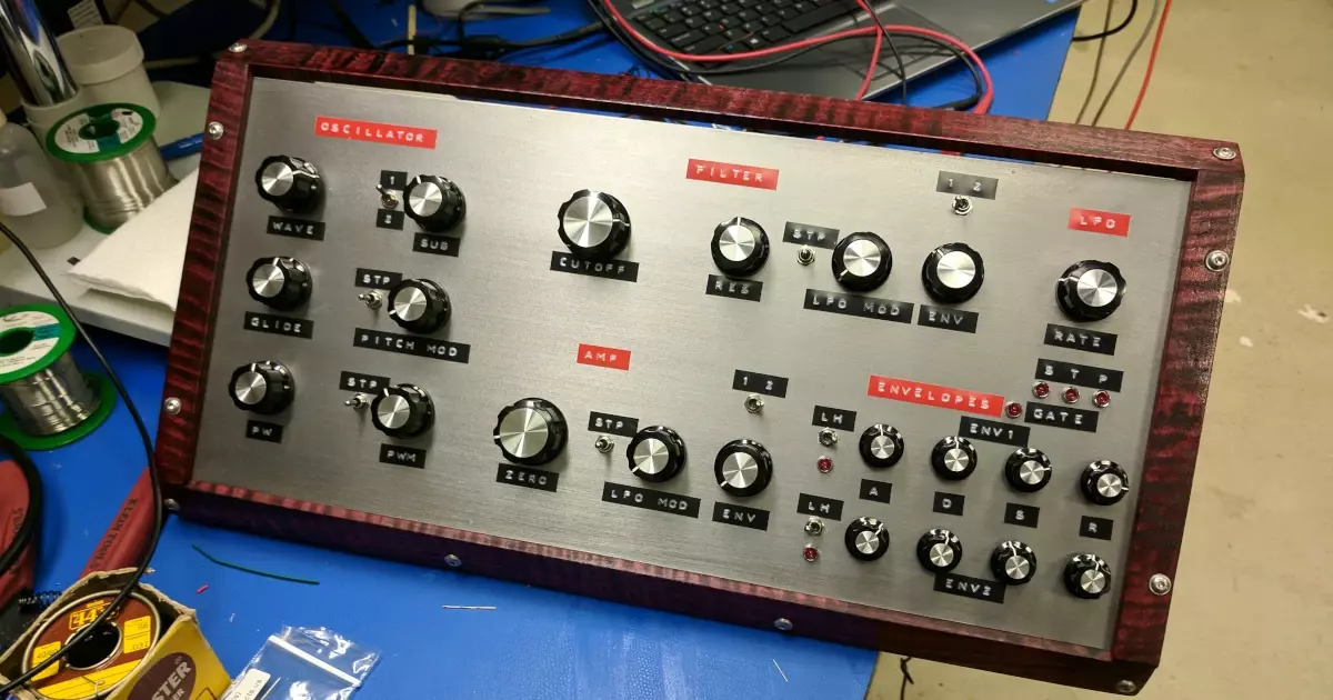
The Venti-Q gets nears completion, USB Type-C example circuit completed, and EE interview topics.
Parker wraps up his Wagon Chime Module and looks at USB Power Switches and Stephen covers his EQ build.
Stephen continues his march into madness with his 20 band EQ amplifier design.
The podcast got mentioned in an article! 12 Great Podcasts for Engineers from the Mind Tribe blog. Mind Tribe is a design driven engineering firm based in San Francisco. The list spawns from a survey from the engineering team at Mind Tribe. Thanks Mind Tribe for mentioning our podcast!
“This is a technical podcast by a Texas-based PCB fab and assembly house where the two hosts (Parker and Stephen) have conversations about electrical engineering. Parker and Stephen provide a unique perspective on hardware and the show is both entertaining and educational.”
Visit our Slack Channel and join the conversation in between episodes and please review us, wherever you listen (PodcastAddict, iTunes). It helps this show stay visible and helps new listeners find us.
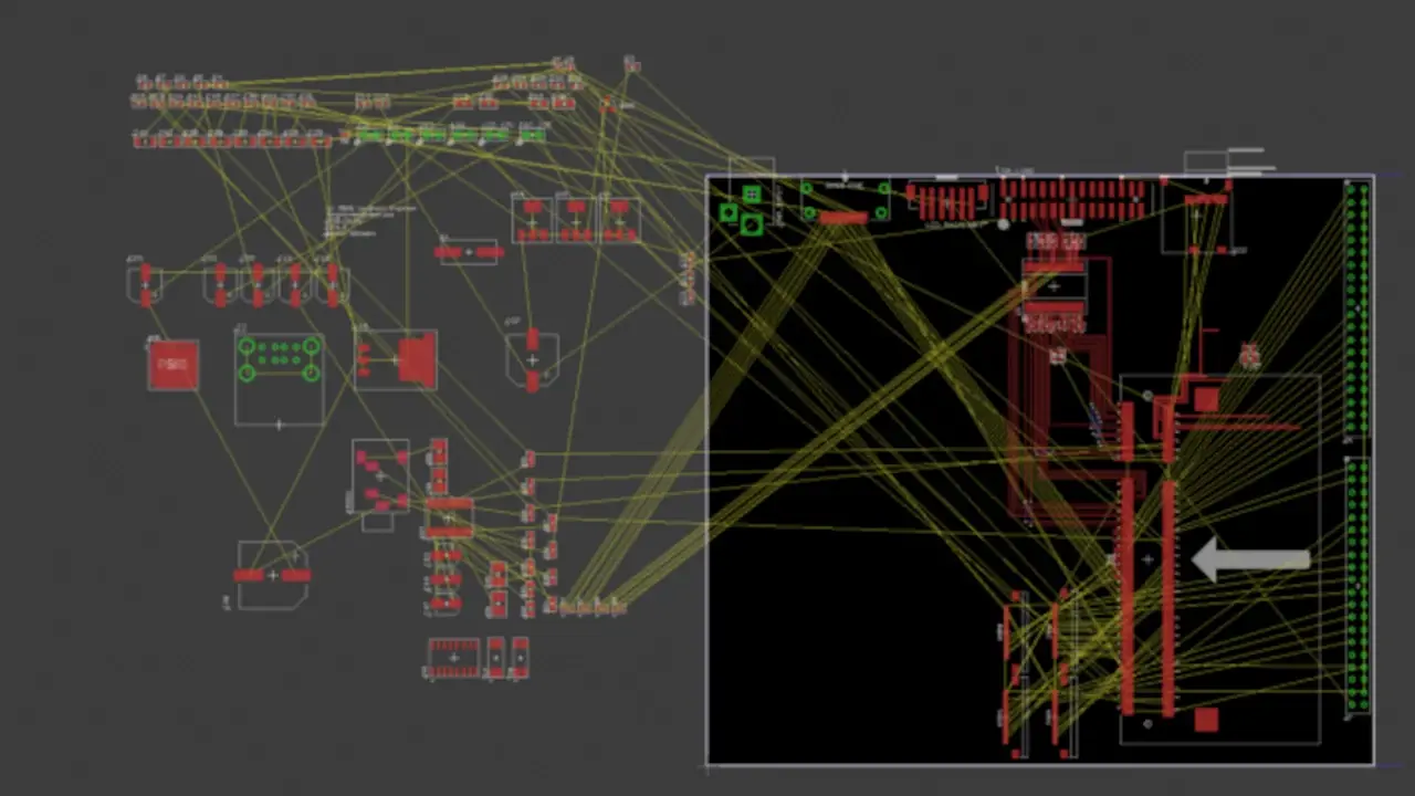
Parker has lots of routing work left on the RPI Compute Module board.
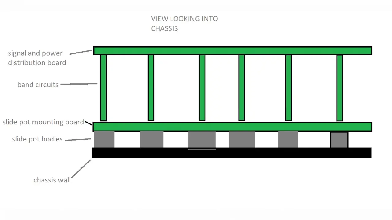
Diagram of the potential PCB stack up for Stephen’s EQ design.
Parker is an Electrical Engineer with backgrounds in Embedded System Design and Digital Signal Processing. He got his start in 2005 by hacking Nintendo consoles into portable gaming units. The following year he designed and produced an Atari 2600 video mod to allow the Atari to display a crisp, RF fuzz free picture on newer TVs. Over a thousand Atari video mods where produced by Parker from 2006 to 2011 and the mod is still made by other enthusiasts in the Atari community.
In 2006, Parker enrolled at The University of Texas at Austin as a Petroleum Engineer. After realizing electronics was his passion he switched majors in 2007 to Electrical and Computer Engineering. Following his previous background in making the Atari 2600 video mod, Parker decided to take more board layout classes and circuit design classes. Other areas of study include robotics, microcontroller theory and design, FPGA development with VHDL and Verilog, and image and signal processing with DSPs. In 2010, Parker won a Ti sponsored Launchpad programming and design contest that was held by the IEEE CS chapter at the University. Parker graduated with a BS in Electrical and Computer Engineering in the Spring of 2012.
In the Summer of 2012, Parker was hired on as an Electrical Engineer at Dynamic Perception to design and prototype new electronic products. Here, Parker learned about full product development cycles and honed his board layout skills. Seeing the difficulties in managing operations and FCC/CE compliance testing, Parker thought there had to be a better way for small electronic companies to get their product out in customer's hands.
Parker also runs the blog, longhornengineer.com, where he posts his personal projects, technical guides, and appnotes about board layout design and components.
Stephen Kraig began his electronics career by building musical oriented circuits in 2003. Stephen is an avid guitar player and, in his down time, manufactures audio electronics including guitar amplifiers, pedals, and pro audio gear. Stephen graduated with a BS in Electrical Engineering from Texas A&M University.
Special thanks to whixr over at Tymkrs for the intro and outro!
Welcome to the macro fab engineering podcast. We are your hosts, Steven Craig and Parker, Dolman. And this is episode 148.
So the podcast got mentioned in an article, the articles title was 12 great podcasts for engineers. And it was written from a blog called Mind tribe. They did not pay us to say this, but mine tribe is a design driven engineering firm based in San Francisco. I ripped that right off their website.
Sweet. Just a little bit here. Yeah,
a little bit. The list spawns from a survey from the engineering team at mine tribe. And so we got listed with all the greats of the engineering podcasts. And so it's one of those, we made it.
There. I don't know what there is, but we're there. We're there.
And my favorite is the the I have the review here and is it's this is a technical podcast by Texas based PCB fab and assembly house where the two hosts Parker and Steven have conversations about logical engineering, Parker and Steven provide a unique perspective on hardware and show and the show is both entertaining and educational. unique perspective
as the word unique perspective, yeah, like they just have to kind of like well, it's, it's unique. You know.
The thing is, most of our reviews are like that.
Yeah, they don't they don't start off with like, this is educational, or this is you're going to learn something or this is going to be really good for you. They're gonna be like, Well, I mean, you know, they're unique.
Yeah, it's, we're different. We're different. Yeah. Mac Feb engineer podcast, the other engineering podcast.
That's really sad actually. Mac Feb engineering podcasts. Were not the amp hour.
Oh, shots not fired. Well. Now, I love you guys. Chris gamble. If you're listening out there. We love you.
We love you, Chris.
Okay, so I've been working on the Raspberry Pi three compute module board, it is almost ready to go build more fiberglass or fr 4am. I added the PCM 5122, which is that that I was I to s DAC that I was talking about, like six months ago. It's finally on the board all routed up ready to go. I've added the land 9514 which is the USB hub and Ethernet controller that is on the actual Raspberry Pi's themselves. Now the compute module doesn't have a built in USB hub or a built in Ethernet controller. And so this is the chip they use. So I basically stole the design from them and put it on my board. So that should be kind of working. I got most of the schematic figured out there's a couple more little things I need to do. Like I need to find the right crystal to make this part work correctly. I've been working more with FM eight microcontrollers. I got their universal B. Dev board. And it's similar to other other dev boards. It's got a screen on it and a bunch of other physical space invaders. It has Space Invaders preloaded on it. Oh, yeah.
I thought that was so cool. When Gosh, was like right at the beginning of like three years ago. Yeah, yeah, we we we both gotta what a sleepy,
sleepy bees. Yeah, no. Standard bee. The bee. There's the honey bee.
I remember. Like, we both turned them on and found out that it had space invaders and we both yelled. And like the whole shop was like what the hell just happened? We're like Space Invaders
getting pre loaded on board. Who's ever idea was that at Silicon Labs? Kudos.
Yeah. High five on then. And and they have the source code for it too. Which Yes,
well, the first thing you did was just make you sped it up by like 1,000,000,000x. And so basically turned it on, it's a game over because they landed immediately.
I was just trying to Jack around with the firmware and be like, What is this variable do
and so I've been working with the universal B which is different than like the sleepy B or honeybee. It's not called the honey bee but whatever. Silica labs if you want to use that for your normal bee line. You can have it royalty free Um, it has USB built into the chip like it has the own USB stack and all the hardware needed, like the differential pair stuff built in. That's awesome. And I was playing around with some of their, their example code like you can do a native comport over it. Now, it's not like the normal comport driver, like Windows and Linux normally use. It's a VCP driver, which I don't know exactly a virtual comport. I think it's what it stands for, but it's like a different driver. It doesn't come native in most operating systems. You right, but it does work. And it works really well. Well, Windows
will detect it, and it has to install the driver for it.
Yeah,
yeah, that's the not the FTDI. But all those little extra like comport cables that you can buy, you know, like the crappy ones, you can get it fries and stuff, they all show up as a VCP. Okay,
so this one, no, I had to like, install the Silicon Labs specific driver work. And I've been connecting that up to basics I want to just, I'm one of the units will be just so I can start playing around with with that comport stuff over USB. Mainly because the next kind of secret project I'm working on. It needs like less stuff on the board, like at the minimize how much like my board is only like, one inch by one inch, what's a little bit bigger than that, but it's about that size. And so I needed, like, minimize what parts on it. So I can't have like a serial UART bridge, because it just takes up too much space. So I went with this native USB microcontroller. And it's still like only like, 25 cents in quantity. It's like, how do you get a, like, an F t 230? X is like minimal, like a buck 50.
Right, right. Or you could just have the microcontroller with the stack inside. Yes, that's
right. And I mean, of course, it takes up some space or whatever, but like, this thing I'm working on, doesn't use that much program space, and or that much RAM or ROM or anything. So it's like, I can really condense it down to what it needs to do.
Okay, I'm gonna I'm gonna do a little bit of a. Well, okay, so I know a little bit about your secret project, which will I guess you'll announce in a second. But but just a quick question. That's purely from me, not the listeners. Are you doing everything in an algorithm? Because I would have expected that you would have had to use more memory?
Oh, okay. Well, the listeners can listen this part. Okay. So so the other part of this is, it's using the SP 7735 screen module thing, which is a common SPI TFT screen, the one I'm using is like a 1.44 inch, which is 128 by 120 pixels. And so what Stephens asking is, how am I basically displaying 128 by 120 pixels in like, not a lot of
space. Yeah, exactly. That's what I'm getting at. Yeah, yeah.
So the images that it's displaying, there's not a lot of pixel depth, like, there's only like, I think there's only like 11, or 12 Different colors total. And so it's using a lookup table to on the fly. So when the cereals actually spitting it out, it's actually looking it up and spinning.
is ripping through an array basically.
Yeah, well, yeah. So it goes, Okay. Since I only need 12 colors, it's only what is that only three, three bits, four bits, four bits, it's only four bits per pixel, instead of two to the, or was eight bits, something like that. Anyways, it's using a lookup table to do it. And then it has a base map. And then everything changes based off that because there's only like 14 or 15 different different images that's going to display, and it just uses a change. Now, it's about 60 to 70% of the pixels change. So that might not be worth implementing, like a, that's kind of like a key frame way of doing it. That might not be the best way to do it. I'm still playing with it, but it's a lot less pixels than you would think is needed.
Yeah, well, the screen is small. And there's not a lot of color depth.
There's not a lot of color depth. Because when you think about it, sure you need like the full eight bits that the screen does to like represent the colors correctly. But you don't need all eight of those bits. You only need like, three.
I didn't I just didn't know if you were if you had come up with like a really fancy algorithm to calculate what the screen was supposed to do at any one point in time.
No, now, that would be cool. Yeah, it would be but I guess Oh, you could like make it an equation.
Yeah, so I'm talking about making an equation that like, you know, it's, it's basically you have two inputs, you have your x and your y, green, and it spits out color.
You know why I'm gonna try that?
Then you want to do anything in memory, you just store the equation.
Yeah, cuz actually, what you can do is you can store the equation for each frame. Uh huh. And then that only has to go to 1212 different colors. Yeah. And then you're you. So you do that to calculate what color needs to go to. And that goes to the lookup table. And that spits out that eight bits. I want, I want to see that's possible. See if I can make a it'd be an Excel. best fit line.
I guess what you could do is just consider the consider the screen to be one continuous line. Yeah. And then just write the equation for like that huge, whatever the line that is, what is 100 something times, however many is in the direction. Yeah. And then when the equation
is one the screens 128 by 128. But when this plane is like 30 by 30.
Oh, we need the whole real estate.
Yeah, so you don't so what it does, it does well, I'm what my driver does, is does nearest neighbor, and so it goes, Okay, it's gonna be this color for the next eight pixels. And just close that over. So that's also how you get lower amount of RAM and ROM usage.
Right, that makes sense? Yeah. Yeah. But it would be pretty cool to have none of your images actually stored. That. Yeah, I
want to try that. Because that might work. I don't see why. That'd be pretty crazy. If it does work.
Related in real time, that's the biggest thing.
Well, real time enough. So that this is a secret project. I'm not gonna say exactly what it is, but it may do everything.
Oh, and doom is capitalized all the letters.
Well, and the notes Yeah.
intent.
So that's gonna be that's gonna be a fun project, because it was kind of like one of those like, receiving I came up with it. What, two weeks ago, a week ago or something like that. I'm like, stop all the presses on all my personal projects working on this now.
Yeah, we both started like immediately just hammering Google was like, Okay, we gotta we gotta research this kid. We do it.
And then I have a wagon update. But this is not gonna be a typical wagon update. Because trying not to do too much car stuff on the electronics engineering, podcast, right?
Welding welding is electronic right?
Anger, electronics, angered fix these, right? Yeah, angry pixies as AP II would say. So I've been putting up YouTube videos on my YouTube channel, have my updates. So go check those out if you want to stay up to date on the wagon, because, I mean, I put bolt in hole a doesn't make for a very good podcast.
Well, I mean, he and go posted on the Slack channel. And anyone who wants to go see Jeep videos. Check that out. Yep. Cool.
Yeah. So Steven, your updates. So I,
let's see here. For a lack of better terms, I feature creep my way into some new designs. And I put feature creep in in quotes, mainly because this is something that I've had kind of in my backlog of to dues for a long time. I just pulled it out of the bag and was like, Okay, now it's time to do it. It's not like a new idea. It's just finally like, Okay, we're gonna do it. Now.
It's been known that like Notepad, like stored away forever.
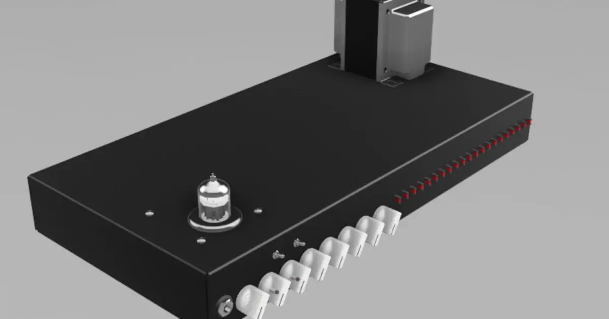
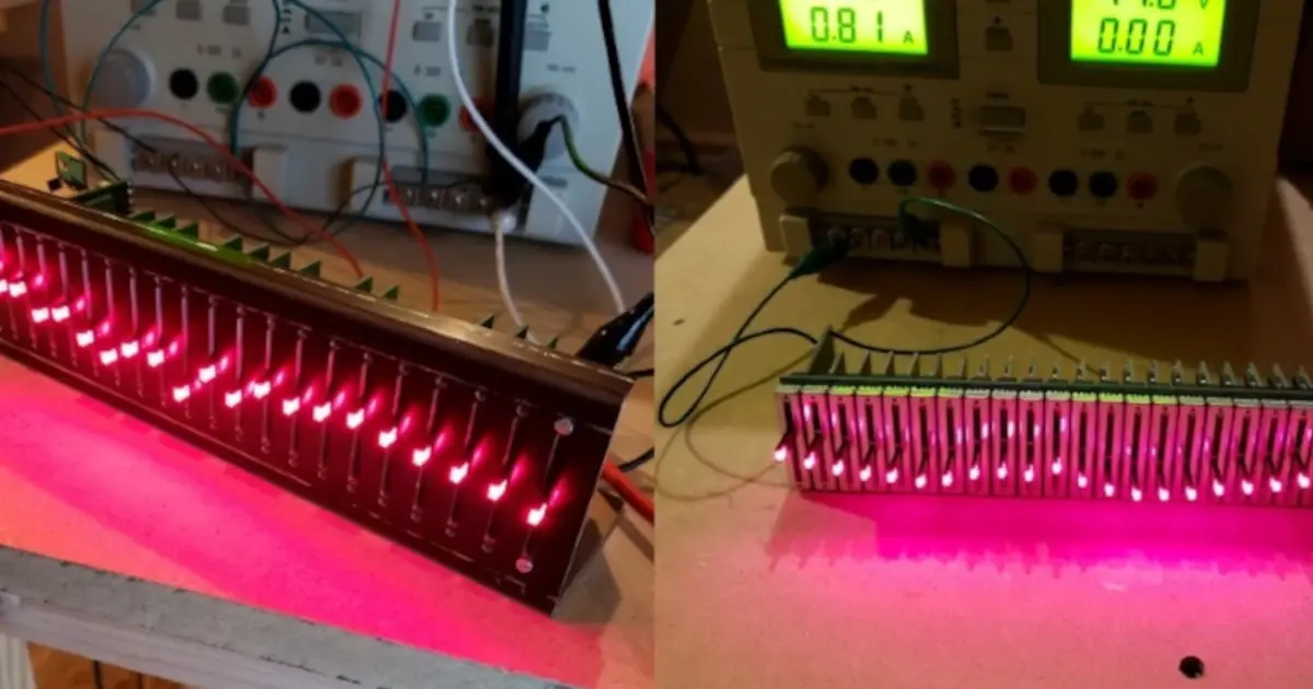
Yeah, that no peg that's like inside your skull way in the very back, you know, I've wanted to design a graphic equalizer for a long time, very long time. And I just never really got around to it, mainly because I didn't have a need for one. But in a previous podcast, I was discussing that. I was getting into a lot more into Fusion 360. And I was designing an app from scratch in a 3d space. And one of the things that I kind of ran into is with the electrical design, I was only using half of the chassis in terms of where my mom put the rest of the guts were actually still taking up, you know, the remainder of the chassis. So it's not like I could cut my chassis in half. But I was looking at it one day and realized that there was just enough room on the other half of the chassis that if I just filled it with a 20 band graphic equalizer, it would fill the whole front panel and look gorgeous. So it was like okay, well obviously I have to go design an equalizer. Yeah. So So I spent quite a while now and got an equalizer kind of thrown together. And
this is not feature creep. This is a, a solution looking for a problem.
Yeah, that's a good way of putting it, I like that blank real estate and I had to fill it with something minus will be electronics, right? Where my nose will actually be something useful. So the the thing is, I'm trying to use this equalizer inside of a tube amplifier. Well, so it's gonna go at the junction in between the preamp and the power amp, because that's, that's a pretty decent spot for you to actually shape the frequencies before they get, you know, is there
is there a reason why you don't want to do that before the preamp? Well, it all
depends on what you're going for. In fact, you know, I think there's a pretty good argument that it would be good to have both, but in between, you sort of get to shape the frequencies of the harmonics that are generated in your preamp as opposed to shape the the frequencies that go into your preamp. So if you have an EQ before the preamp, then you can somewhat adjust not somewhat, you have a pretty powerful connection with the harmonics that you'll generate. So you can control the clipping, you know, if you scoop out 500 hertz, there's a lot less chance that you're going to distort 500 hertz, and just not as in like heavy distortion, because every preamp is going to distort. So being able to fine tune all of those things. And actually, good decent example of all of this is the one, the main guitar that I play on has an awful, awful peak at about 210 hertz, it just resonates like crazy at 210 Hertz. And I don't like that it sounds terrible, in my opinion. So I, a lot of times, I'll put a notch in that area, and it cleans everything up. And all the other frequencies are allowed to just come on through. And so this EQ is going to allow me to kind of like shape that a little bit, I may also do some other things to adjust that. But regardless,
it makes the most sense. In my designed to go in between the branch and the power amp. The problem is the output of my preamp is tube level. So it's upwards of 200 volt peak to peak swing, there's no solid state device that's going to be able to handle 200 volt peak to peak. But my power amp is expecting a huge signal like that, too. So I had to kind of finagle a solid state solution that would drop that. So I had to do a 50 to one division effectively. So 200 volts would be a maximum of four volts, which I've got plenty of headroom to handle four volts. And then at the end of it, I had to, you know, basically do a recovery gain stage that brings four volts back up to something in the I don't know, big range, it's it's not super critical what it is for what I'm going for. So I mean, I don't get me wrong, I calculated my gains, but it's not. It's so dependent upon where the user puts the knobs that is not, I'm not super worried about being like there's exactly 3.56 times gain here, you know, like, in my opinion, like my design has enough gain, that enough gain. That's where I'm at with that. When the equalizer I was a little bit more anal about getting everything right, because if you're trying to do a graphic equalizer, and you have your band stepping over each other, then it's not a good equalizer it doesn't. So I used a multiple feedback bandpass op amp configuration to establish the gains of each one of my bands. And since I'm doing a 20 band equalizer that's using a one kilohertz standard.
That means that each band is one kilohertz wide.
No, no, we'll be each each band is going to be you know, bands in the lower frequency range are going to be smaller in terms of their frequency span. And bands higher up in the frequencies band are going to be wider. Okay, the thing is, they all have the same q and the q is the quality factor of a filter. And if you remember back in, I guess, I guess that was college. That's the first time I really started playing around with with Q Q basically determines how I guess you could say sharp or how high the peak of a filter is. It's a lot more than that. But effectively, we weren't
like what's the term attack?
Yes, sort of. Yeah. Well, I guess if you're talking about if you talk Okay, let's I guess we'll define it here. If we're talking about a bandpass filter, and you look at the center frequency, let's say the center frequency is that 1000 Hertz. If you look to higher frequencies and lower frequencies, look at where the negative three dB point is. Take the difference of those two frequencies and see how wide that is. You can calculate the mean that that is that's your bandwidth. is what they basically call it, and then you one divided by that you can get the cue. Um, okay. So when it comes down to designing a graphic equalizer, you want every band to have the same cue, but it won't have the same bandwidth, it'll, it'll be, you know, some will be wider your, the bandwidth of a band out at 1500 hertz is going to be a lot bigger than the one that's at 60 hertz, because 60 hertz only has to go from something like 42, up to 100. And something, I don't remember the exact numbers, but regardless, so I'm using a one kilohertz standard, and on a 10 band EQ, each band is one octave. So one octave would be half of a, you know, a kilohertz would be, I guess you'd be at 500 hertz would be the low end, and then 1500 on the top end. But since I'm doing a 20, band EQ, there's one more band in between there. So I'd have one band at 1k, one band at 751, band at 501, at 375 250, blah, blah, blah, you can follow that all the way down. And
I was really shooting for what's called a constant q filter, which there's sort of hard to design around and a constant q filter is based off of however you have it set, the cue will always be the same. So what it really boils down to is that each band doesn't affect other bands, it's more isolated into its own little bucket. And I sort of got a constant cue designed going in sort of as in like, it's not perfect, but it's pretty close. It's enough. It's enough. Yeah, exactly. It's like my gain. It's enough. Well, and the thing is, like I'm not doing like Studio Mastering or anything like that. Yeah. And, and the actual, like, relative position of the of the knob, even though it's linear, and I could probably determine exactly where like specific gains are on that knob. It doesn't matter in Guitar World, like you just turn it and be like, do I like this yes or no?
Well, and also, like potentiometers are like plus minus 20%. Exact like, you'd never going to get perfect from like, you know, unit A B, unit B is not going to be the same.
Oh, for sure. And the thing is, I'm using all slide pots, because it's a graphic equalizer, that all have a center detent and the slide pots with a center detent are notorious for not being center at the center. So even even if you have this thing all zeroed out, and the front panel shows zero across the board, I bet you you know, there's I haven't measured it, but there's once I build it, maybe I will, I bet you there's half a dB of difference across each band from even if it's everything's dead center. So, but each band I designed to have a plus minus 12 DB range. So it's pretty powerful. I mean, it will that's pretty standard. But But that's, that's really powerful when it comes to guitar guitar world. Crusher add a bunch of gain was tough. But you know, as a one of the things that's interesting is, with graphic equalizers, getting the right taper on a potentiometer is really tough.
So, like a linear slide potentiometer, you would think that that would work pretty well, forgetting, you know, as you go up, you get more gain as you go down, you get less gave it. But but most of these designs end up being a complex feedback design that doesn't work linearly. So as you go up, you'll you don't get a lot of change. And then the very the last 10% of the slide on the slide pot does like a Yeah, so it was like three dB for 90% of the travel and then eight more for the last little bit. So what it what it really ends up being is like these on off switches. So there's the solution to that is to get a different taper on a pot and they call it a W taper. So you know how there's like linear and logarithmic and reverse logarithmic and that there's a special taper for slide pots, that's a W taper, which is log and anti log log in one direction, anti log in the other direction, going from the center. And basically lied pots are meant only for graphic equalizers. Those are the only points
and they're super hard to find. And I didn't want to design around that. So I actually came up with a different solution on that where I used
2164 VCAs to act as a voltage control potentiometer and so I can use the regular slide potentiometer linear slide potentiometer to control a voltage controlled potentiometer and then that and that goes to be logarithmic and anti logarithmic. Yeah, yeah, exactly. And I and I also kind of made it where if you if you're in the center of your slide pot, then both of the VCs are at zero. So you you basically you You're passing Unity game, if you if you move the slide pot up, then it only activates one of the VCAs. And that VCA is working. So for boosting the boost VCA is working. And then if you slide the slide pot down from center, only the cut VCA is working. So they don't work all the time. In a traditional equalizer, where just relies on a on an analog potentiometer, you're always sharing both sides of the pot unless you're at the maximum or the minimum. But in my design, it depends on where the potentiometer slide is. And that actually ends up working really well for for what I'm doing, and I've got a lot more control over it. So I did a lot of work and probably spent way more money than just going out and getting W taper pots, even if I had to have them custom made, because I made all of this like sub circuitry just to get around a taper
Well, or at least the simulation show that it works out really well. So that sometime soon,
you should add a I liked the 20 band idea, but then have a a not a nice slider notch slider not wanting to have a potentiometer that will that will shift the frequency from like, let's say is like one hertz all the way up to 20 kilohertz, right? And then a lever to go up and down to do your DB boost or gain or so it's a sliding notch that you could have also on top of this this band. Okay, yeah, well, okay, you can pick like I want, I want 162 hertz, because that's what my guitar resonates at and sounds bad. So I want to basically put that zero and slide that around until I hit that, and then you can play around with the other stuff.
Well, okay, so check this out. This is pretty cool. So the I mentioned that the core of each one of my bands is a multiple feedback, multiple feedback, bandpass configuration, op amp it go go look it up, there's a Wikipedia page on it, and all the equations and stuff like that are on there. So the cool thing about this type of layout or this type of design with this EQ is you can change what the core of the EQ is. And it just responds to whatever the core you chooses. So if you just put a high pass filter there, then now you have a controllable high pass filter, if you put a anything, it will just control that. So instead of a multiple feedback, bandpass configuration, you could put a state variable filter, which takes three op amps, but what it gives you is control over the individual cue of each band, it also gives you the bandwidth of each band, and it'll give you what is it the frequency so So exactly what you're talking about could still be done in the analog realm. It's just when you think about it, that adds three more potentiometers to each band.
You just have one of these on your,
your Oh, so you're just saying like add an extra notch somewhere in there. Yeah. So
it's like you have this 20 band that's like sets, like it's a normal equalizer set up, then you have a notch that you can slide around if you need it.
Okay, yeah, well, I mean, exactly what I just said,
Put one state variable filter in it with a with a cut boost and a sliding filter on there, and then you then you have exactly what you're talking about there. So that's not a bad idea. Maybe I'll do that. Actually, at the end of the 20 band EQ, I put a makeup gain on it where I basically I have one extra slider where if it's in the center, then it's unity gain, if it's down at zero, and then if it goes up, it gives you a gain of two. So I wanted to have basically a master control that if you leave it in the center, it's not there. But if you need just one more fine tune on the global volume of everything you can do it may go to 12
Yeah, if that one has six dB of gain, I apologize. 16 DB. Just so six. Okay.
So basically, I have that whole thing, the schematic all created for that and it's ridiculous. I can't remember it has something like 400 components on the board, like I just went overboard on everything. Like it was like I I'm not designing this for mass production right now. You know, like, I'm just doing it for my one off amp. So I'm just gonna make a super EQ, you know, just for fun. So I hope to hope to build that and I have to lay it out and that's the part that's I love layout but this one is going to be 20 step and repeats over and over and dip trace doesn't do Step and Repeat as good as Eagle does. So I basically have to do the same thing 20 times for every component you know.
You could do is auto route it man. Yeah.
Even I think I'm
starting to catch on fire right now.
Yeah. Grand is opening up, you're gonna fall in. So that's what I've been doing.
Oh, hoping to see when you get that whole board done.
Yeah, I'm pretty excited about it, actually. So one quick little update. One thing I'm thinking about doing is ripping out the core, that multiple feedback core on each go through the core. So what I'm thinking about doing is having a header where that core basically you have input output grounded power.
And I was thinking about making separate boards that you could plug in. So if you wanted to do a state variable, core, you just plug that core in, or if you want to do multiple feedback. And that's more just for fun and more to like, try out different things. Because if I just build in the multiple feedback, feedback thing, like that's all I get it right, you know, that's it. So I don't know, if you
do it that way, though, you only have to draw that one board once and just get 20 copies of it, instead of said redoing it all the time. So now you just have to put headers on the main board.
Exactly, yeah. And that was it also makes the I'm space constrained, even though like the whole point of making this EQ was to use up the space, I have too much circuitry for this space now. So I have to get creative on how I'm actually doing it, you know, and that brings up another thing. So I came up with a with a really interesting footprint that I'm going to be trying out on this board. So I have some really really really nice coax cable that I inherited from a previous life. And this this coax cable, I want to solder the coax cable directly to my PCB. And the footprint that I've created has different pads on top and bottom of the board which, frankly, dip trace doesn't handle differing pads on top and bottom very well. Eagle does that pretty good, right?
You'd have to make two s&t pads and then plunger hole on it.
Okay, that's, that's not that great either. No, no,
it's not. That's how you would do it.
Basically, with dip trace. The best way that I can find to do it is to make a hole with a small annular ring. And then draw the rest of your pad how you want it to be on top and bottom.
I guess I guess that would work in Eagle too.
Yeah. See, the thing is what Okay, so here's what I'm wanting to do. I have a hole going through the board. And on the side that my coax enters the board, I want to have the whole the annular ring, and then basically a space and then a separate pad that the coax solders to throw the coaxial solder flat against the PCB, and the center conductor will go into a hole inside the PCB. So basically, what I have is a pad that is inside of a pad that they're not connected to get out there. So it's confusing but I designed something up and dip tissues is throwing all kinds of DRC errors at me but whatever I think it's
I know this will work don't challenge me
you know, that's that's another great but
it's like you draw it and you're like I knew you would say that DRC tool.
Oh gosh, yet exactly.
Judge Dredd
doesn't have a really good option for for letting you say like, No, it's okay. I know what I'm doing in this situation like dickface will always be like Hey, dude, this is bad.
The eagle has an A has a approved button. Yeah, he just like basically ignore it.
No, I was like that about Eagle because when I was doing DFM reviews in Eagle there was a lot of times that it was throwing crap where it's just like no like this one. Legitimately. I understand. And it's it's kind of like when you're when your smoke alarm goes off in the kitchen when you're cooking. Yes, it would be nice to just have like an automatic be like Nope, it's okay. Don't worry about it. I got this like, that's just some smoke, you know? Yeah,
it's I open up the oven. It's fine. Yeah, yeah.
Okay, cool stuff onto the
arco, which some people don't know what the RFO means. That's true. It's the rapid fire opinion, which when we first started this podcast 100 And whatever episodes ago, it actually meant rapid
and we originally intended it to be where we would just say something and then at the end of it both Parker and I'd be like, thumbs up or thumbs down, you know, like it was supposed to be something like that.
And well, we originally started this podcast and each podcast was like sub three 30 minutes. And we're already at like the 35 minute mark. Which frankly, I think ended up working better, the slightly longer form tends to be better.
Yeah, well, it allows us a chance to release our unique perspectives on hardware. Right? Exactly. Okay, so the first the first item on our RFO this week is STM releasing STM. 32, cube MX version 5.0. And for those who don't know, that's STMS configuration software for their STM 32 line of microcontrollers. And so just a few days ago, I believe it was November 21, they released their 5.0 version, which, you know, if you're a regular, a regular user of STM 32, that might be old news for you. But it's pretty cool. I saw some videos on it. And it looks like they really cleaned up a lot of stuff. So over the summer, I started getting into STM 32 configuration and pretty
ballsy to that right before like Thanksgiving.
Oh, yeah. Yeah. Because that's what it was at the office. Table, right? Yeah. So so this, this configurator, I always thought that it was it was pretty good for the for the STM 32. It was just slightly clunky. Some of the stuff wasn't really straightforward in terms of where you go and what you have to do in terms of configuration. But it looks like they cleaned up the UI. And they made things sort of like a left to right path, where you just start off, you define your pins, then you walk to your clock, and then you walk to power and you're blah, blah, blah, you go down the line. And at the end of it, it just dumps out to your IDX the full configuration file. And they made it like the graphics look a little bit nicer this time around. So it's pretty cool. Look at cool.
I got to check it out.
Just a quick question for you on that, because this actually brought up an eye an idea when I was looking at earlier today is I'm curious what your path is when you're you so you've already selected a microcontroller for your project, you already know what you're going to do. Not always well, but no like just Britain. Go with me on this just did you already have selected that? Okay, what do you do first? Do you define your pins? Do you define your clock? Do you figure out your communication? Like what is your method?
So let's say with the EFM? Eight? Yeah. Okay. So what I usually do with the estimate is I actually this is actually a good thing is this is my entire like embedded software process from a high level
everyone. Please give us 599 Right now
if pencil and paper out and apparently write this down. So I do is I get the all the hardware like hardware, like the sensors, all that stuff, get those designed, get that ready to go figure out what kind of protocols I need to talk to them like do I need I swear see, do I need spy? Do I need DMA and some some cases? Get all that good go. And so basically, once I figure that out, I can go shop for a microcontroller. Okay, okay. And I always pick, like the beefiest, microcontroller first from the line, right? So I'm like, Okay, this one has enough IO to run on my buttons and all my sensors and all that stuff. Basically, guaranteed will do it. Yeah. And then I'm gonna pick the one with the largest amount of RAM and the largest amount of ROM, build that and get that board manufactured. And while that boards been made, I start writing the code, get the code written, get get basically like making sure basically when the board shows up, I can put that code on and make sure my hardware works all right. So it's basically just like talks to like all eyes proceed devices, make sure the spies working right, all that stuff. Generally doesn't work the first time. green wire, all that good stuff. Basically, you get a working board all the hardware is working, got that good. Then start filling out your code, getting all the functionality working all that stuff. And then optimize, optimize, optimize your code and then shrink your ROM and RAM on your your microcontroller into like, it's like the minimal it can be ie it's like the cheapest microcontroller of that line. Got it? That's my approach. So basically, like, I guess in terms of like, specking out like when you're in the IDE, is I usually do like IO first, because I need spy I need I squared C I need maybe I need TX RX, serial or USB. Expect that stuff out first and then do IO. And once I get that, I actually go back to my schematic, and then make sure that lines up in my schematic, because sometimes you have to change some, you know, IO lines around. Yeah, then go look at your board and make sure you can route that. Yeah. And sometimes like, oh, I can't route that, or it's going to be, you know, via hell. And so then you go back to your IDE and go, Okay, can I? Which ones of these can I swap around to make it better? And basically work back and forth that way until I got something that looks nice and a fan out on the microcontroller? I think this is why I think a lot of embedded designers need to know more about like the IDE world, maybe not like programming, but at least like knowing what Chip functionalities can be, you know, put onto a pin.
Oh, absolutely. You have to, you have
to, you can't just assume, you know, well, like sometimes, like, you'll have like a pin. And it's like in your schematic and it's labeled what functions that can be. But sometimes, that's not the whole story. Sometimes that function can only be used there if that port is set up that right way. And so you have to go through that process first.
Even that only works if another port is set up a certain way. Yeah,
sometimes that's the case. If a mate seem to be a lot more generous in this, because they have that crossbar, and a lot more, like more modern microcontrollers are starting to have this like a 10 can be anything kind of thing. Yeah. Which is really nice. But as it's always good to go back to the back and forth, you know, juggle between IDE and your schematic until everything looks good. Yeah. So that's my process there is I pick pick the pins and that kind of stuff. And usually clock lines have to be clock lines, there's not really any way to get around that even in like these microcontrollers with cross bars. Generally, they have like these pins are used for clocks, because they have probably special routing inside the chip.
Cool. There's there's the secrets into parks and secret sauce. Anything but there you go. Cool. So yeah, go check out the STM 32 Cube MX version 5.0. Or at least go watch a video of it. You know, I'm sure our listeners will actually know what's going on.
I know a lot of like old school engineers don't like these hardware configurators they save so much time learning platforms. I like them a lot. I really liked the the hardware configurator and EFM eight, it just makes learning the hardware like you don't have to go hunt for that one stupid register that you have to set the mixer that pin doesn't use it as a comparator. And so you can use as the GPIO pick 16
You also don't have to read like 1000 Page data sheets, you know what I mean? You don't have to read them as intently let's say you only have to read 300 a4 pages of that 1000 Page data sheet
it does help out a lot now that's not the end all because I have run into issues where like some modules were like conflicts and stuff like that but well I'm sure
it's hard for them to keep track of everything too. Yeah
you think they made it they know everything about it right?
She's there's a lot of information in there a lot. Yeah.
Well you got to think is it wasn't one person who did that entire data sheet or one person designing the whole thing. So
good god I hope not. I feel sorry for that guy.
So cool. So the next RFO is I'm looking for a CNC router. And so I've been looking at options online to pick one up. So this is kind of like a general question to our listeners is like what kind of if you have a CNC machine or have a suggestion for a CNC machine let me know my specifications is like a two foot by four foot CNC router. It's basically me cutting plywood and sometimes aluminum but mostly just plywood and plastics. I've been looking at the what is this the CNC router parts CRP 4824 router kit, because that kits about two and a half grand and then you have to add electronics and all that other stuff to it, but it seems to be a pretty rigid structure for the cost. And it basically does everything I need to do. And then I was going to build a vacuum table for it and we were talking about this before the podcast but like you can like the CNC machine can build its own vacuum table by just punching little tiny holes. Little over the sacrifice boards billboard. Yeah. And I have like a two horsepower vacuum pump. I think it actually is bigger than I think so four horsepower vacuum pump leftover from a a stencil machine. You rescued it rescued it before it went to the garbage.
Yeah, I've seen on Parker, I've seen a handful of PVC designs that actually work really well for vacuum tables. In fact, I saw one that was really cool. It was it was on a four by eight CNC where he had it set up into quadrants. So you don't have Bart's? Yeah. And he had a he had each one valved. So if he knew he was only going to use one quadrant, no need to, you know, pull a vacuum on the entire table. So he just set it for whatever he needed, which was, I thought that was a really great idea.
Yeah. So and we also had the idea of, Hey, we should bring a guest on to the cop podcast about maybe some DIY CNC stuff, but instead of just like, you know, buying X parts and then cobbling it together, but like, going into like the science and engineering of actually building a DIY CNC, like picking out lead screws, like motors specifications, like stepper verse servos. How do you control those stuff like that?
Yeah, and even even some ideas on like, here's what's new to the industry, maybe not so like salesy, but like, on the controllers, you know, maybe there's something that's some magical widget out there. That's really great for it. So if anyone knows anyone who is, you know, really well versed in CNC designed for probably more on the DIY side of things, we'd love to have a guest on, I think that would actually be a really fun topic.
So let us know in our Slack channel, or emails that podcasts@macro.com
How do they get to the Slack channel, Parker? Go to
our podcast notes, and there's a button there that says slack?
How do they get to our podcast notes?
I credit.com/blog/podcast. I actually think.com/podcasts works as well.
Yeah, I think it does. So yeah, that would be that would be great to know, I'm actually looking to rebuild my CNC in the future also. And so I want to get away from a chain driven design and go to a lead screw design. So I have done some research on
rack and pinion man. Well, the
rack and pinion rack and pinion would be great. However, you know, also, on that topic, I did a handful of torque calculations, torque versus speed, because that's from everything that I've learned with CNC, like torque versus speed is it's a compromise in both directions, right? So rack and pinion is great, but you kind of have to spec your motors, right? For retina kind of you absolutely have to spec your motors, right? For that kind of thing. And when it comes down to it, lead screws work really, really well and you get pretty dang good accuracy.
So I think you have less backlash. Yeah,
it all depends on what you buy. And well actually, you know, all depends on how much money you throw out the problem, right? And you can get you can get basically no backlash if you if you throw a bunch of money at it. But okay, so you got speed, you got torque, you got backlash, but you also have transmission, you know, do you want to couple your rack and pinion through a transmission? Well, what if you do a lead screw with a half an inch pitch on it? Is that enough? Torque probably but how fast you have to turn that thing to get the acceleration that you want. And you know all of these kinds of things that would be fun to talk about. I have an Excel spreadsheet somewhere where I did a bunch of calculations on like, Okay, I know I want my CNC to do this. And I basically back calculate Yeah, that calculated from if I wanted to cut aluminum what motor would I need? You know like but you have to go backwards through a whole bunch of stuff a whole bunch of you know losses and calculations or engineering whoo.
Oh, yeah. So the last topic for the RFO is the cheese burger compass. So this is a stick this is a GPS and Raspberry Pi combination with like IOT to let you know on a little tiny screen where the nearest cheeseburger fast food places and like miles and directions so you can always find that greasy cheeseburger that you would want to let into your heart and soul.
And I think it had like if it pulls from a list of like a few 1000 Cheeseburger places, so it's always like finding where you are in relation to cheese.
I thought that was a really cool project in and I was like man that is just straight to my heart.
Yeah, so this is the I guess you can find some information on Patrick mcdavid.com/cheeseburger-compass. We'll put that in the show notes. But yeah, that's that's freaking amazing, huh? Maybe we need a taco finder.
Ah, yeah. Or brewery finder. Ooh. Yeah, that's great. That's a good idea. So that was the Mac fab engineering podcast. We were your host, Parker, Dolman. And Stephen Curry. Go find a beer or taco or a burger right now. Take it easy, everyone thank you. Yes, you are listener for downloading our show if you have a cool idea, project topic or cheeseburger compass that you want Stephen and I to discuss, tweet us at Mac fab at Longhorn engineer or at analog E and G or emails that podcast at macro rev.com. Also, we totally like talking about cheeseburger compasses at our Slack channel. So go click that and join up. If you're not subscribed to the podcast yet, click that subscribe button. We should be having a mailing list soon for the podcast as well. So check out our blog and click the mailing list and sign up so you can get the latest episode right when it releases. And please review us wherever you listen as it helps the show stay visible helps new listeners find our very unique perspective on hardware engineering.
Parker wraps up his Wagon Chime Module and looks at USB Power Switches and Stephen covers his EQ build.
Stephen continues his march into madness with his 20 band EQ amplifier design.
The Venti-Q gets nears completion, USB Type-C example circuit completed, and EE interview topics.