The Footprint Files – Electrolytic Capacitors
When designing footprints for electrolytic capacitors it is important to place clear indicating marks to show the components’ orientation. The importance of polarity cannot be overstated in these capacitors. Mistakes in polarity can harm not just the capacitor, but other components on the electronic circuit as well. A product's success can depend on the precision and clarity with which components are marked.
Since this style of capacitor is polarized, meaning they have positive and negative poles, they must have indicating marks on the PCB to help determine the correct orientation during placement. Incorrect placement can disrupt the dielectric properties, potentially leading to a shorter lifespan of the capacitor or immediate failure.
Clarity in marking electronic components is key to making sure that the manufacturing of your design goes smoothly and the blue smoke does not escape your capacitors. Beyond the immediate component functionality, consistent and clear markings help streamline the PCBA manufacturing process. Assemblers and technicians rely on these markings to place components efficiently. Any uncertainty can slow down the assembly process or, worse, lead to mistakes that are costly to rectify.
The tantalum electrolytic capacitors are even more prone to catastrophic failures when they are energized backward due to their unique construction and sensitivity to reverse voltage. It is possible to damage tantalum capacitors by reversing polarity, but it is also possible to damage the surrounding board and other devices as well.
The Electrolytic Capacitor
Electrolytic Capacitors are one of the most popular types of capacitors used on board design. Their popularity stems from their efficiency in storing large amounts of charge in a relatively small form factor. They are low cost and provide a good balance of physical size and capacity.
There are four physical flavors of electrolytic capacitors; SMT Can, SMT Case, PTH Radial, and PTH Axial. Each style is marked slightly differently. They are usually marked with a band on the cathode side of the capacitor indicating the negative terminal but there are some exceptions. This is different from the typical schematic symbol which is positive or anode marked!
Electrolytic Schematic Symbol
The typical polarized capacitor will look like the image below on the schematic. The positive or anode side of the capacitor is marked with a “+” symbol. When drafting a schematic, it's important to maintain consistency in symbol use to ensure that everyone reviewing the design can quickly understand the intended orientation. Since electrolytic capacitors are polarized, I use a symbol (shown below) on my schematics.
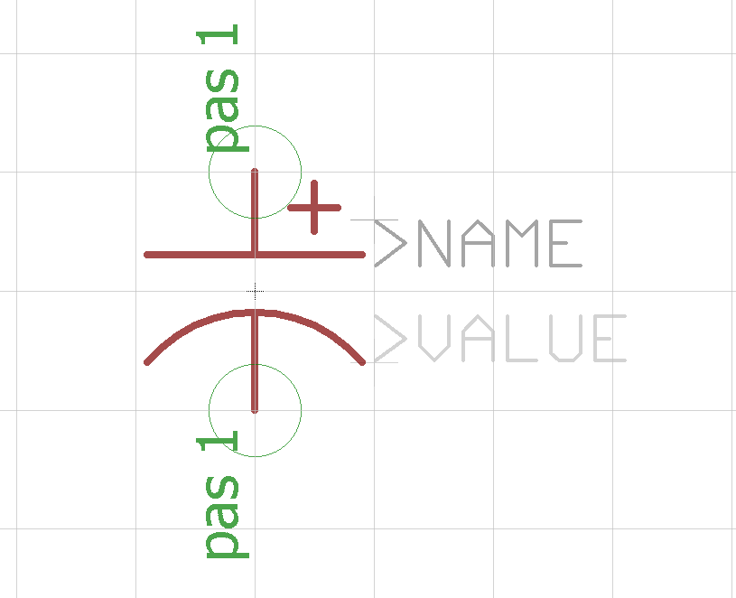
Capacitor Polarized Symbol
Schematic symbol for polarized capacitors as shown in Eagle.
SMT Can Style Electrolytic Capacitor
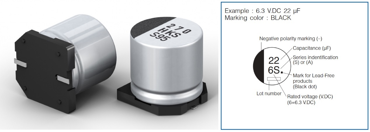
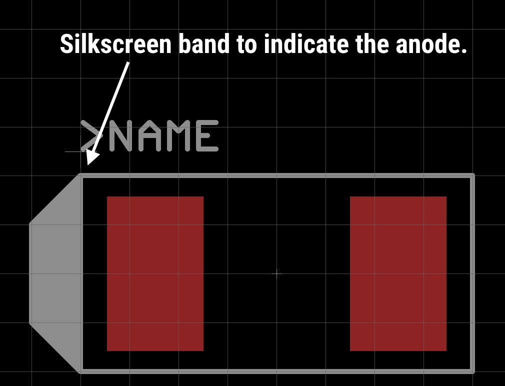
These capacitors are marked on the top of the can with a black mark. The mark’s color sometimes depends on the manufacture however. The plastic base of the capacitor are also chamfered on the positive or anode side.
Smd cap
SMT Can Electrolytic Capactor: Marking indicates negative or cathode side.
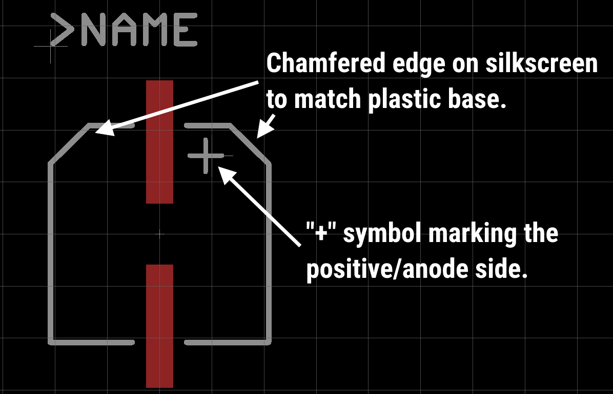
SMT EL Footprint
Footprint of a typical SMT can electrolytic capacitor.
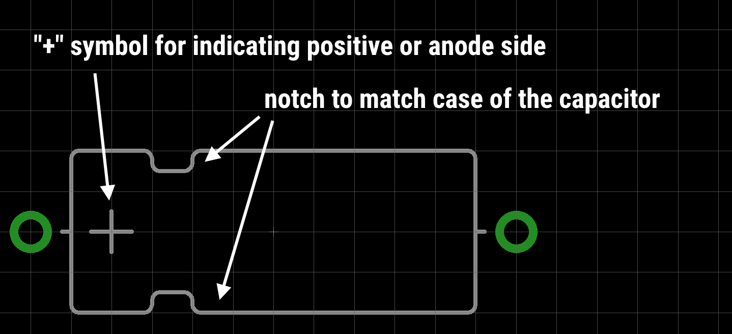
SMT Case Electrolytic Capacitor
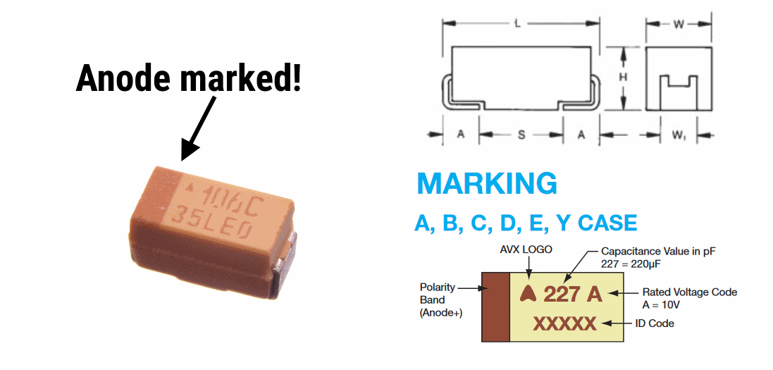
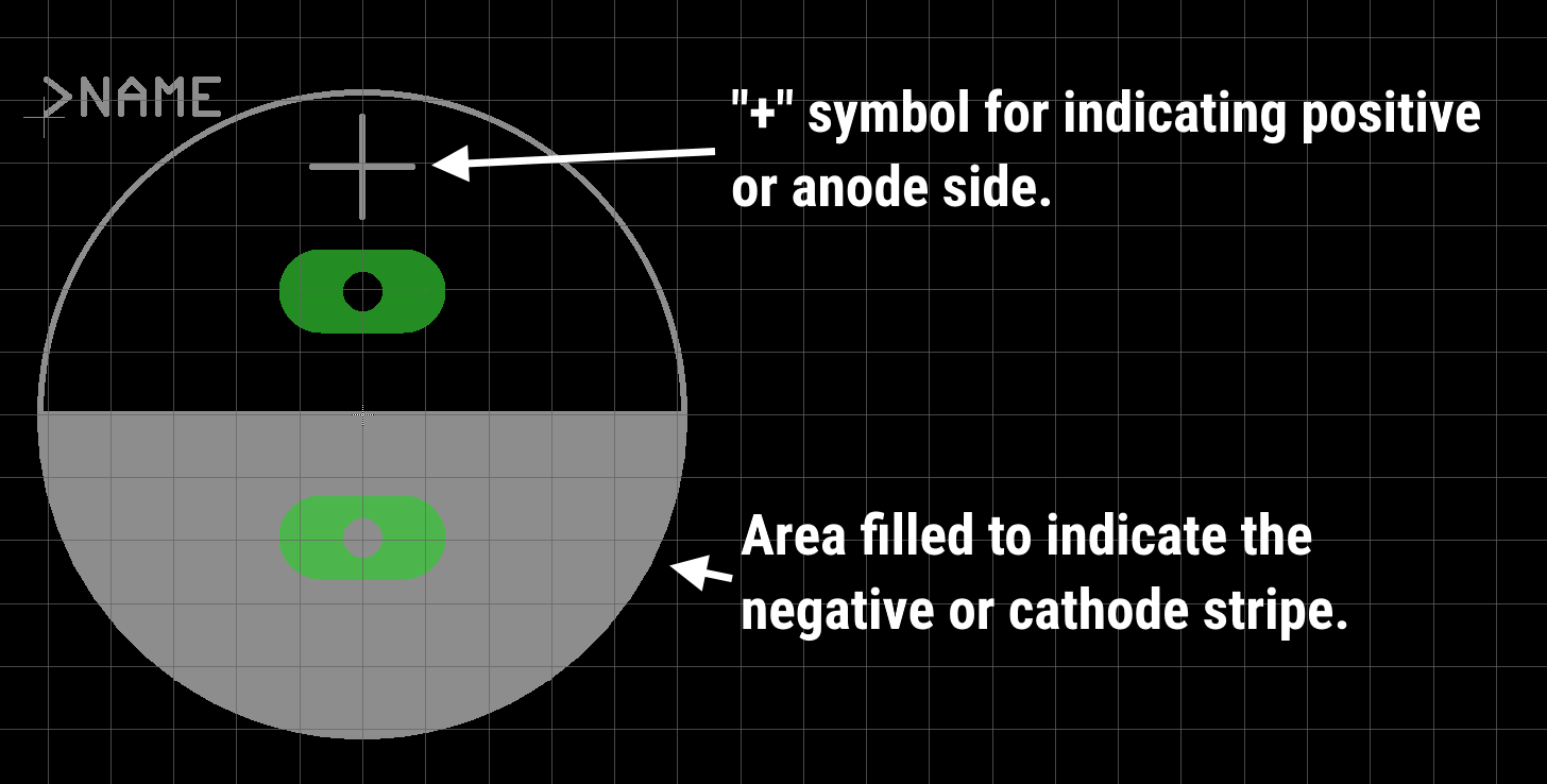
Capacitors of this type usually have tantalum or niobium inside but there are a few polymer electrolytic. Case style means it is shaped similar to a 0805 resistor or ceramic capacitor. Unlike the other packages for capacitors, these are typically positive or anode marked.
SM Tcasemarking
SMT case style electrolytics are usually anode/positive marked. Watch out!
SM Tcasefootprint
Footprint for SMT case style electrolytic capacitors.
PTH Radial Electrolytic Capacitor
Radial caps have both the anode and cathode leaving one side of the capacitor. 99% of the time these are marked with a contrasting strap down the cathode or negative side of the capacitor.
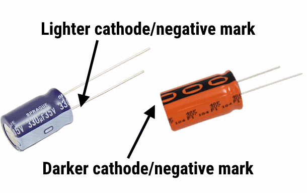
PTH Radial Markings
PTH radial polarized electrolytic capacitor markings.
PTH Radial Footprint
Footprint for PTH radial style electrolytic capacitors.
PTH Axial Electrolytic Capacitor
Axial style capacitors are not used very often but are interesting in how they are marked. A negative or cathode band runs down the side of them similarly to the radial style but there is an arrow in the marking that indicates which side is negative or the cathode.
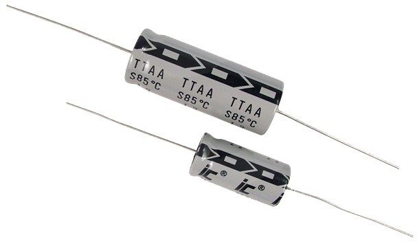
PTH axial style electrolytic. The cathode strip points towards the cathode.
PTH Axial Cap
Footprint for a PTH axial style electrolytic capacitor.
Next Time on the Footprint Files…
The most important thing to remember is to check your parts data sheet and see how the polarity is marked on the part. Learn more about reading Electrolytic Capacitor datasheets from MEP Ep #196: Foamy Power Factors--Electrolytic Capacitors with KEMET.
Copying how the part looks on your board's silkscreen will guarantee much higher success during the assembly of the board. I hope this will improve your footprints on your board and make your products and prototypes easier to build. Next time on the footprint files we will be discussing tantalum capacitors.
Check out the previous post in this series: The Footprint Files – Diodes
Was this post helpful? Are there other topics you’d like us to discuss? If so, let us know on Twitter.
Related Topics
The Footprint Files – Diodes
Designing footprint files for diodes requires clear orientation marks. Learn what to do and when you can break footprint rules in this blog post.
Get Started Today
Get an Instant Quote NowAbout MacroFab
MacroFab offers comprehensive manufacturing solutions, from your smallest prototyping orders to your largest production needs. Our factory network locations are strategically located across North America, ensuring that we have the flexibility to provide capacity when and where you need it most.
Experience the future of EMS manufacturing with our state-of-the-art technology platform and cutting-edge digital supply chain solutions. At MacroFab, we ensure that your electronics are produced faster, more efficiently, and with fewer logistic problems than ever before.
Take advantage of AI-enabled sourcing opportunities and employ expert teams who are connected through a user-friendly technology platform. Discover how streamlined electronics manufacturing can benefit your business by contacting us today.