Red Hot PCB: Additive Robotics Motor Control
This week’s featured PCB comes from Additive Robotics and is an integrated interface for brushless DC (BLDC) motors. The board basically allows you to control, sense, and cool an attached motor, in a way that is very efficient in terms of form factor, weight, and power.
The board was developed for use in high-end educational robotics kits, for Huston-Tillotson University (HTU). The board (and supporting hardware) will be used as the primary actuation system of the kits, powering the wheeled robot designs created by the students. The kits will be used to teach a variety of real-world robotics techniques (ranging from basic electronics / mechanical design to real-time embedded programming to advanced sensing / navigation algorithms) at HTU.
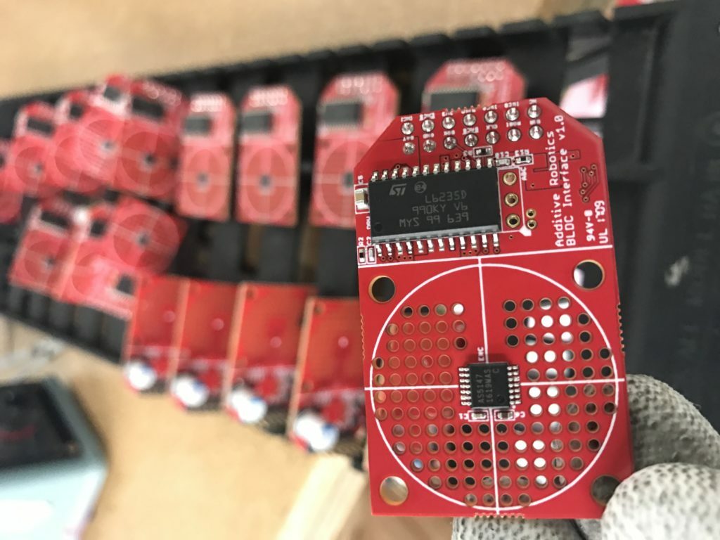
A little more about the PCB; the encoder (AS5147, centered in the circle) measures the encoder’s position based on a magnet attached to the motor’s shaft. It provides configuration / data access via SPI and also generates three-phase commutation signals (required to drive the motor) and incremental encoder signals (used by a microcontroller). The encoder also allows for the zero position of the motor to be configured via SPI. This allows the timing of the commutation signals to be optimized at run-time, improving the performance of the motor. The motor driver (L6235D013TR) uses the commutation signals to drive the three motor phases (turning on and off the electromagnets at exactly the right time to maximize motor torque). The driver is also current-controlled, which improves both the accuracy of motor control and the safety of the device (the motor won’t burn up when stalled).
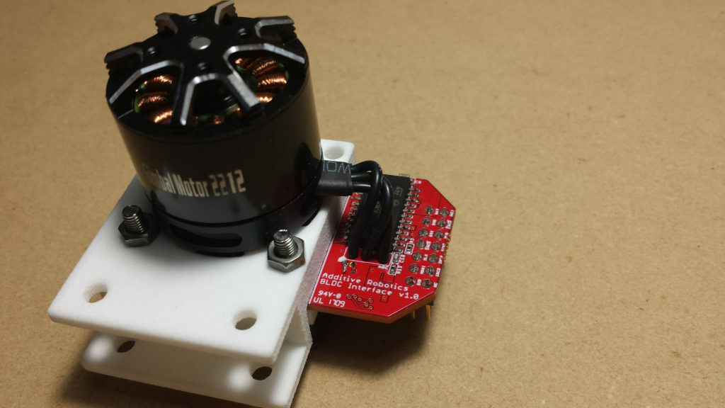
Motor submodule top 1024x576
A small fan, powered by the on-board regulator and mounted behind the board, pushes air through the holes and into the motor mounted in front of the board. This allows a single fan to cool a small motor and the driver circuitry at the same time. The cooling is important because it increases the power density of the actuation system, by increasing the maximum current the motor can handle without overheating. The system is also very flexible in terms of motor selection; you can use any brushless motor as long as you can attach a magnet to the shaft and align it with the crosshairs on the board.
Many thanks to Josh with Additive Robotics for providing us with thorough details and additional photos!
Did you enjoy this post or find it helpful? Let us know in the comments below!
Related Topics
MacroFab vs. PCB Manufacturing Brokers: Why Direct Matters
This blog explores the key differences between MacroFab and manufacturing brokers, and why direct manufacturing is the optimal choice for PCBA needs.
Ultimate Guide To PCB Schematics: Concept to Prototype
A comprehensive guide for navigating early design phases and utilizing schematics alongside Gerber and drill files during the PCB creation process.
How MacroFab Uses Clear Communication to Improve Your PCB Production Experience
This blog will discuss how MacroFab can help customers in their PCB production experience through clear communication in a high-octane environment.
About MacroFab
MacroFab offers comprehensive manufacturing solutions, from your smallest prototyping orders to your largest production needs. Our factory network locations are strategically located across North America, ensuring that we have the flexibility to provide capacity when and where you need it most.
Experience the future of EMS manufacturing with our state-of-the-art technology platform and cutting-edge digital supply chain solutions. At MacroFab, we ensure that your electronics are produced faster, more efficiently, and with fewer logistic problems than ever before.
Take advantage of AI-enabled sourcing opportunities and employ expert teams who are connected through a user-friendly technology platform. Discover how streamlined electronics manufacturing can benefit your business by contacting us today.