Power control for products used to be as simple as just cutting off power source to the device but in recent years devices have become more complicated. The advance of IoT devices and light weight embedded operating system environments have created a need for more intricate ways to shutdown these devices. Corrupted or lost data should be a primary concern when developing hardware, and having a safe way to power the devices down is a way to help mitigate those problems. Here I’ll outline several ways to power down your devices.

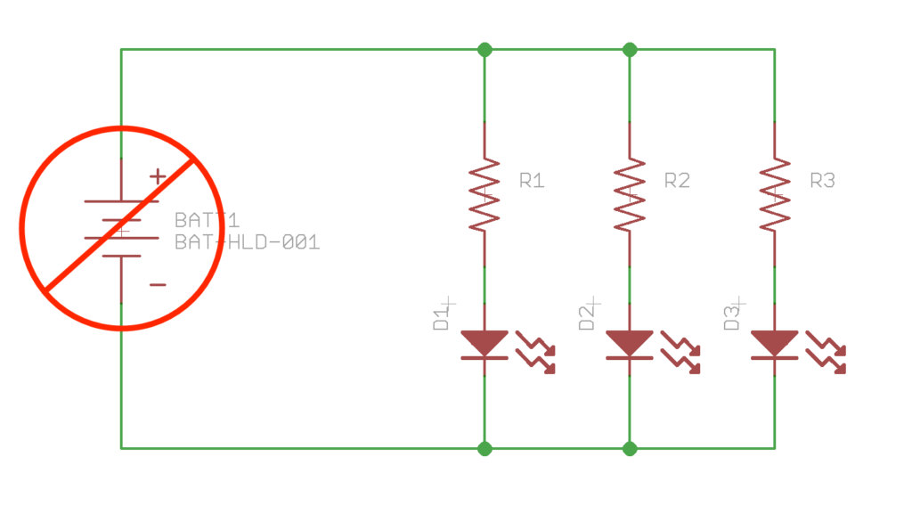
Removal of the Power Source
This seems like the most obvious solution to turning off devices but it is a good solution for inexpensive devices or devices never designed to be off. Some examples are:
- Watches/clocks
- Monitoring devices
- USB devices
- Guitar FX pedals
Most devices that use this technique generally don’t have data that can be damaged with a sudden power removal. USB devices like thumb drives have a “software” lock in that you should eject the drive from the operating system before removing. What this does is allows the thumb drive to reach a state of “safety” with the data stored on its internal flash memory.
Pros
- No Switch, no Bill of Material item. Inexpensive solution.
- Simple to electrically design for, hardware wise.
- Saves the most amount of power, no leakage current.
- Prevents robot take over of humanity by removing the power source. Should be at least a backup solution for an AI controlled device.
Cons
- Possibly annoying to end users. Having to unhook the battery from your car would get old fast.
- Memory and storage corruption problems. Unplugging a USB thumb drive unsafely could corrupt the data.

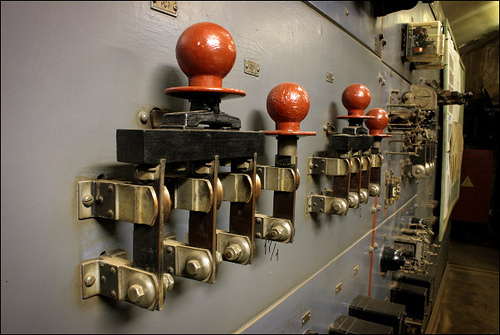
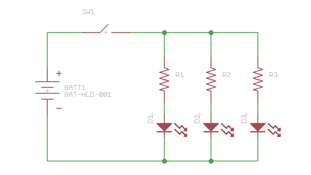
Physical Power Switches
These are components that can physically disconnect the flow of electrons in the power circuit. Toggle, slide, disconnects, and knife switches are examples of switches like this. Usually they are latching style switches, which means the switch holds the position it was pushed or flipped to. Tools, industrial machines, most house appliances, and pinball machines are devices that use switches like this.
Pros
- Easy to electrically design for. Simple Hardware solution.
- Saves the most amount of power, no leakage current.
- Can easily handle large power requirements. Just get a bigger switch.
- Typically easy to repair. If switch melts just replace it with a new one.
Cons
- Can be expensive. Physical parts drive up Bill of Material costs.
- Placement problems on circuit boards. Where you want the user to interact with the power switch might not be where the power circuitry might be. Running big power traces all over the board can cause CE/FCC emission problems.
- Limited to panel mount and through hole switches. Physical power switches typically need a large contact force rating which could rip off SMD pads.
- Memory and storage corruption are still problems with this method.
- Possible additional assembly required for the product. Panel mount switches need wires to go from the switch to the PCB.
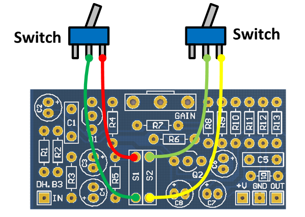
Soft Power Switches
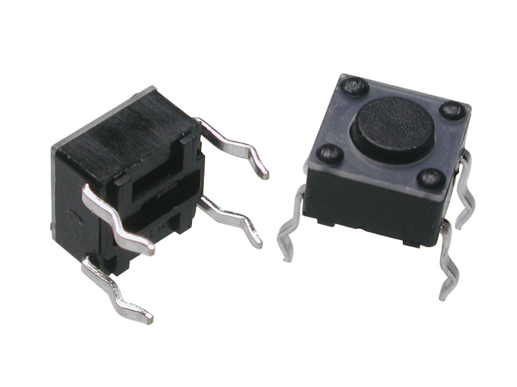
These are switches that control the flow of electrons indirectly using relays, mosfets, or SSR (solid state relays). This works by using a smaller low power switch to turn on the relay, mosfet, or SSR which then turns on the more high power circuit. Soft power switches are typically found in computers, TVs, phones, and consumer devices. More devices are starting to use this method of power control. Tact switches are fairly common, and inexpensive for soft power circuits.
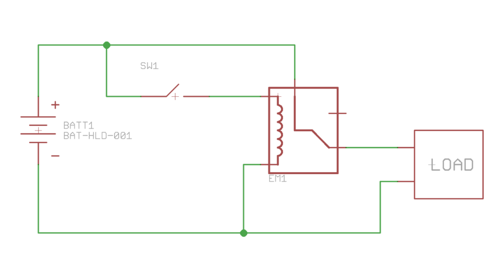
Direct Relay or Mosfet Style
This style of soft power control is typically found in Automotive and Industrial applications for high current and power requirements. This circuit has a switch that allows power to go to a relays coil, a mosfets gate, or a solid state relays input. With this method the only current that flows through the switch is the current needed to activate the relay, mosfet, or SSR. This keeps the high power current path away from the user and it is possible to isolate the high voltage easily. This also reduces the cost in wiring the device. Instead of having to route large power cables to the switch, smaller gauge wire can be used.
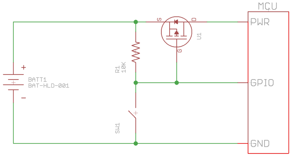
Latching Style for MCU applications
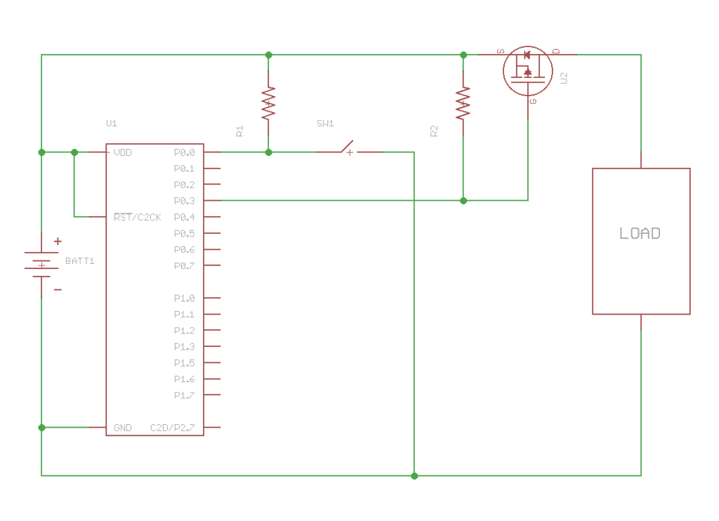
Using a mosfet, tact switch, and a GPIO pin from the MCU, a simple latching style power circuit can be created. In the circuit below, on power up the R1 resistor pulled up the gate on the U1 p-channel mosfet which prevents current from flowing through U1. When the user presses SW1, the gate on U1 gets pulled to ground which allows the current to flow and the MCU turns on. The MCU then drives the GPIO pin to ground. When the user releases SW1 the GPIO pin keeps the gate low. The MCU then just Hi-Zs the GPIO pin when it needs to shutdown. This way it can make sure the data is safe when it shuts down. The downside to this circuit is that the user can not turn off the MCU with SW1 and it uses a GPIO pin from the MCU.
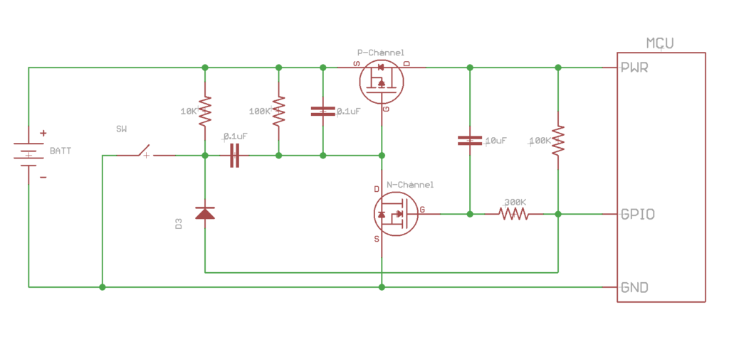
Latching Style with safe shutdown
This is a continuation of the latching style but now the MCU can see the switch SW be pressed by the user when it is powered up. It uses the p-channel mosfet as the power control and the n-channel mosfet to either keep the p-channel open or closed. This circuit is also interesting in that by holding down the switch while the circuit is on for 3-4 seconds it will do a hard shut off which could be useful if the system it controls locks up. More information about this circuit can be found here. This circuit has lots of extra parts compared to the previous example. The MCU can also be placed into a safe state before power off as well to preserve data. When a user presses the switch the MCU can see the state change on the switch through the GPIO pin and initiate shutdown. When the MCU is ready it can drive the GPIO low which will then turn off the circuit.
MCU Sleep Mode
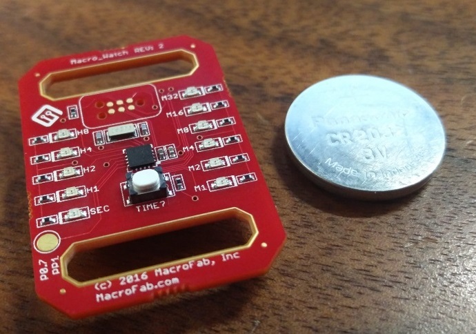
This is a soft power switch that wakes up the device that is in sleep mode. So instead of the switch disrupting the current path it the MCU is in a low powered state till told to wake up. Typically the switch is connected to an edge interrupt. The MCU is then placed into sleep mode and configured to wake up if the edge interrupt is flagged. Pressing the button then “turns on” the system by waking up the MCU. One can go further by placing a p-channel mosfet in series with the rest of the circuit load that the MCU can control to further save on power while the MCU is in sleep mode. This method is becoming more popular in consumer electronics with the advent of IoT devices and energy savings. Below is an example circuit with some code. The MacroWatch project uses this method.
while (1) { PMU0CF = 0x20; RSTSRC = 0x04;
   //Sleep
   PMU0CF = 0x0E | POWER_MODE;

   while (!(VDM0CN & 0x20));

   // Read the wake-up source flags
   wakeup_source = PMU0CF & 0x1F;

   // Clear the wake-up source flags
   PMU0CF = 0x20;

   // Check for switch
   if (wakeup_source & 0x02)
   {
    // Do awake Stuff!
}
}
Pros
- Easy to electrically design for
- Easy to layout
- Low part count
- Inexpensive parts
- SMT Assembly
- System decides when to shut down safely to prevent data loss
Cons
- Device is never truly off
- If system locks up what do you do?
- Requires more understanding of your system to get sleep working correctly
Recap
How a device is powered on and off should be a primary concern for the designer and the end user. Here are some questions to ask:
- Does the device have data that can get corrupt?
- Is it supposed to turn off on the user request?
- Is having good tactile feedback important?
From removing the batteries, physical power switches, and MCU sleep modes there are lots of options to explore. For even more kinds of soft power circuits, Dave Jones with EEV Blog has a video on the subject.
Ready to get started?