Related Topics
Building LibrePCB - Urban Bruhin's Journey in Open Source EDA
Urban Bruhin shares his journey from being an electrical engineer to developing LibrePCB, driven by his dissatisfaction with existing EDA tools like Eagle.
Beating the Heat
The PinoTaur has reached production status but not without supply chain issues..OF COURSE! Bonus discussion about thermal management for PCBA.
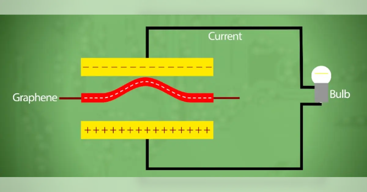
Doing Something Magical
Will graphene allow us to transcend to the next level of existence with free energy? Parker and Stephen discuss limitless power and the iPhone 12.
Other Resources
Circuit Break Podcast
Webinars
Videos
Tour MacroFab's ITAR-Compliant Facility
April 28, 2021, Episode #274
- Thermal Management Part two!
- Interesting thermal management designs and devices
- Copper “fingers”
- Thermal Jumpers
- Interesting thermal management designs and devices
- Common DRC Problems
- Annular ring
- Copper to Board Edge
- Tolerances of the checks?
- Why?
- -0.1mil or -0.00254mm
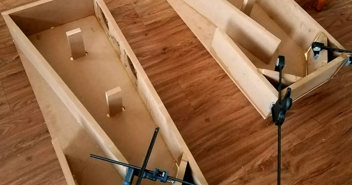
- Record Player Deconstruction
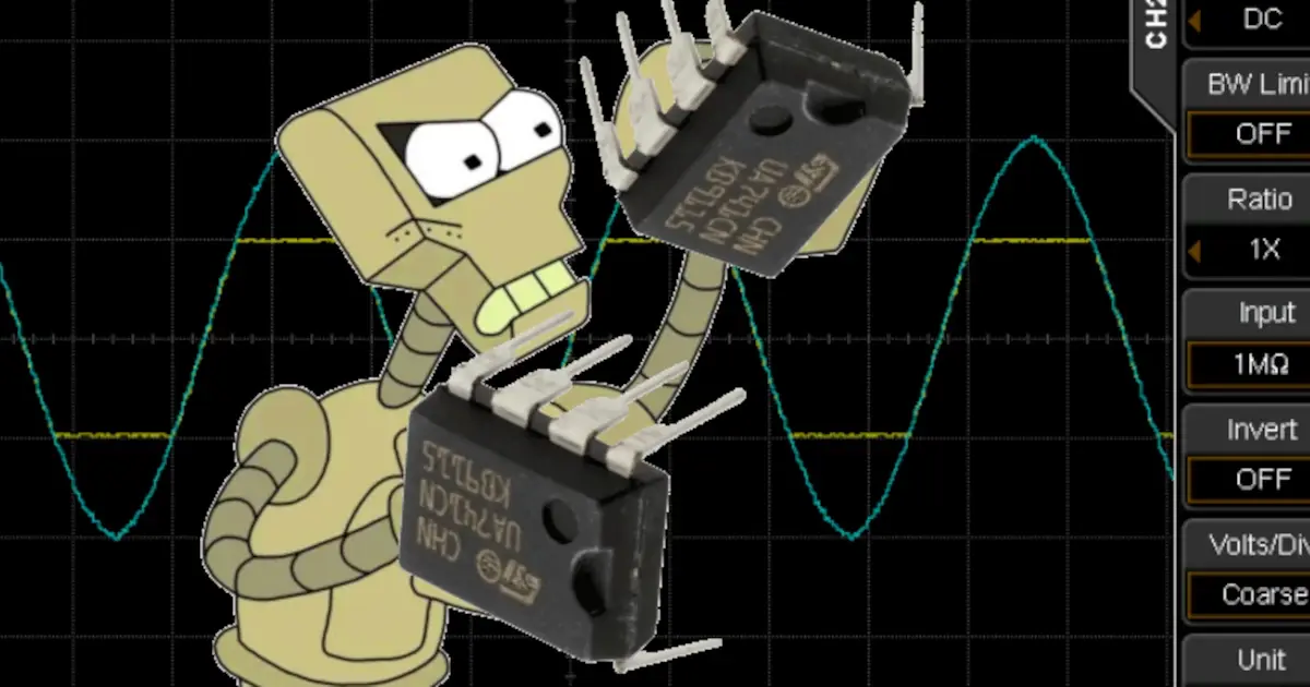
- Tube Amp Schematic
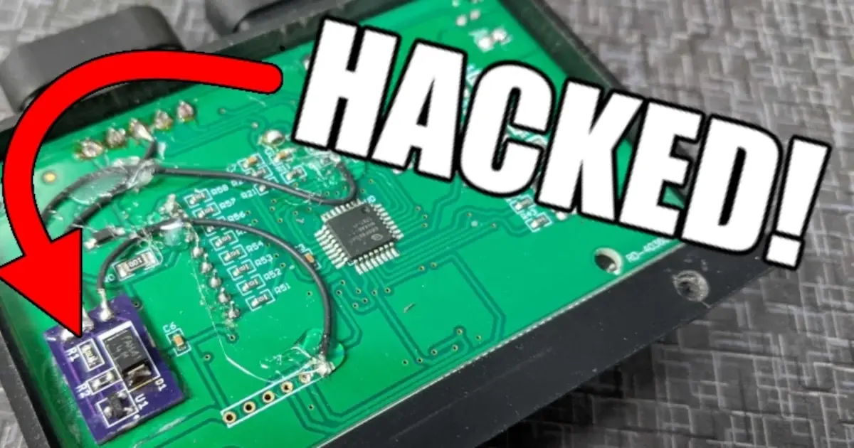
- Possible Fake components?
- From the thermal discussion from last week’s podcast
- LM338 or LM317…
- Opamp Stability
- Interesting issue with opamps and comparators with latest design
- Make sure to add extra component pads for analog design prototyping!

About the Hosts
Parker Dillmann
Parker is an Electrical Engineer with backgrounds in Embedded System Design and Digital Signal Processing. He got his start in 2005 by hacking Nintendo consoles into portable gaming units. The following year he designed and produced an Atari 2600 video mod to allow the Atari to display a crisp, RF fuzz free picture on newer TVs. Over a thousand Atari video mods where produced by Parker from 2006 to 2011 and the mod is still made by other enthusiasts in the Atari community.
In 2006, Parker enrolled at The University of Texas at Austin as a Petroleum Engineer. After realizing electronics was his passion he switched majors in 2007 to Electrical and Computer Engineering. Following his previous background in making the Atari 2600 video mod, Parker decided to take more board layout classes and circuit design classes. Other areas of study include robotics, microcontroller theory and design, FPGA development with VHDL and Verilog, and image and signal processing with DSPs. In 2010, Parker won a Ti sponsored Launchpad programming and design contest that was held by the IEEE CS chapter at the University. Parker graduated with a BS in Electrical and Computer Engineering in the Spring of 2012.
In the Summer of 2012, Parker was hired on as an Electrical Engineer at Dynamic Perception to design and prototype new electronic products. Here, Parker learned about full product development cycles and honed his board layout skills. Seeing the difficulties in managing operations and FCC/CE compliance testing, Parker thought there had to be a better way for small electronic companies to get their product out in customer's hands.
Parker also runs the blog, longhornengineer.com, where he posts his personal projects, technical guides, and appnotes about board layout design and components.

Stephen Kraig
Stephen Kraig is a component engineer working in the aerospace industry. He has applied his electrical engineering knowledge in a variety of contexts previously, including oil and gas, contract manufacturing, audio electronic repair, and synthesizer design. A graduate of Texas A&M, Stephen has lived his adult life in the Houston, TX, and Denver, CO, areas.
Stephen has never said no to a project. From building guitar amps (starting when he was 17) to designing and building his own CNC table to fine-tuning the mineral composition of the water he uses to brew beer, he thrives on testing, experimentation, and problem-solving. Tune into the podcast to learn more about the wacky stuff Stephen gets up to.
Special thanks to whixr over at Tymkrs for the intro and outro!
Related Podcasts
Clipping and Clamping OpAmps
Are rules of thumb obsolete? Validate your thumbs on this episode of the MacroFab Engineering Podcast while Parker discusses progress on the brewery!
Building LibrePCB - Urban Bruhin's Journey in Open Source EDA
Urban Bruhin shares his journey from being an electrical engineer to developing LibrePCB, driven by his dissatisfaction with existing EDA tools like Eagle.
Doing Something Magical
Will graphene allow us to transcend to the next level of existence with free energy? Parker and Stephen discuss limitless power and the iPhone 12.
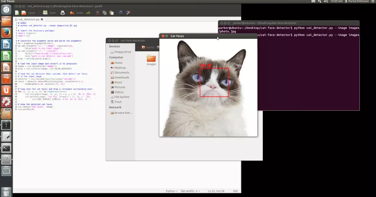
Reverse Biasing Opamps
Parker learns Python and OpenCV and Stephen gets silly with transformers.
Beating the Heat
The PinoTaur has reached production status but not without supply chain issues..OF COURSE! Bonus discussion about thermal management for PCBA.
The Greek Tragedy of ADCs
Battery less Cellphones, Raspberry Pi Compute Modules, ENOBs, and a 100W USB Type C eval board!
About MacroFab
MacroFab offers comprehensive manufacturing solutions, from your smallest prototyping orders to your largest production needs. Our factory network locations are strategically located across North America, ensuring that we have the flexibility to provide capacity when and where you need it most.
Experience the future of EMS manufacturing with our state-of-the-art technology platform and cutting-edge digital supply chain solutions. At MacroFab, we ensure that your electronics are produced faster, more efficiently, and with fewer logistic problems than ever before.
Take advantage of AI-enabled sourcing opportunities and employ expert teams who are connected through a user-friendly technology platform. Discover how streamlined electronics manufacturing can benefit your business by contacting us today.