Improve Your Next PCB Prototype: Better Debugging, Testing, and Reliability
The design and development of PCB assembly prototypes are foundational steps in bringing innovative electrical products to life. As hardware technology advances, PCB designs become increasingly intricate, requiring thoughtful integration of debugging and testing features to maintain reliable performance and support efficient production testing. Skipping this critical step or cutting corners in the prototype phase can lead to costly errors, delays, and the need for expensive rework—making the cheapest prototype actually cost more in terms of time, effort, and money.
Building prototypes with robust testing and debugging capabilities reduces risks and accelerates the path to production. With careful planning and the right tools, engineers can address challenges early, refine their designs, and set the stage for successful product launches without unnecessary setbacks.
This article discusses the essential features you should include in your next PCB assembly prototype to enhance its debugging, testing, and general reliability.
Debugging Features for PCB Assembly Prototypes
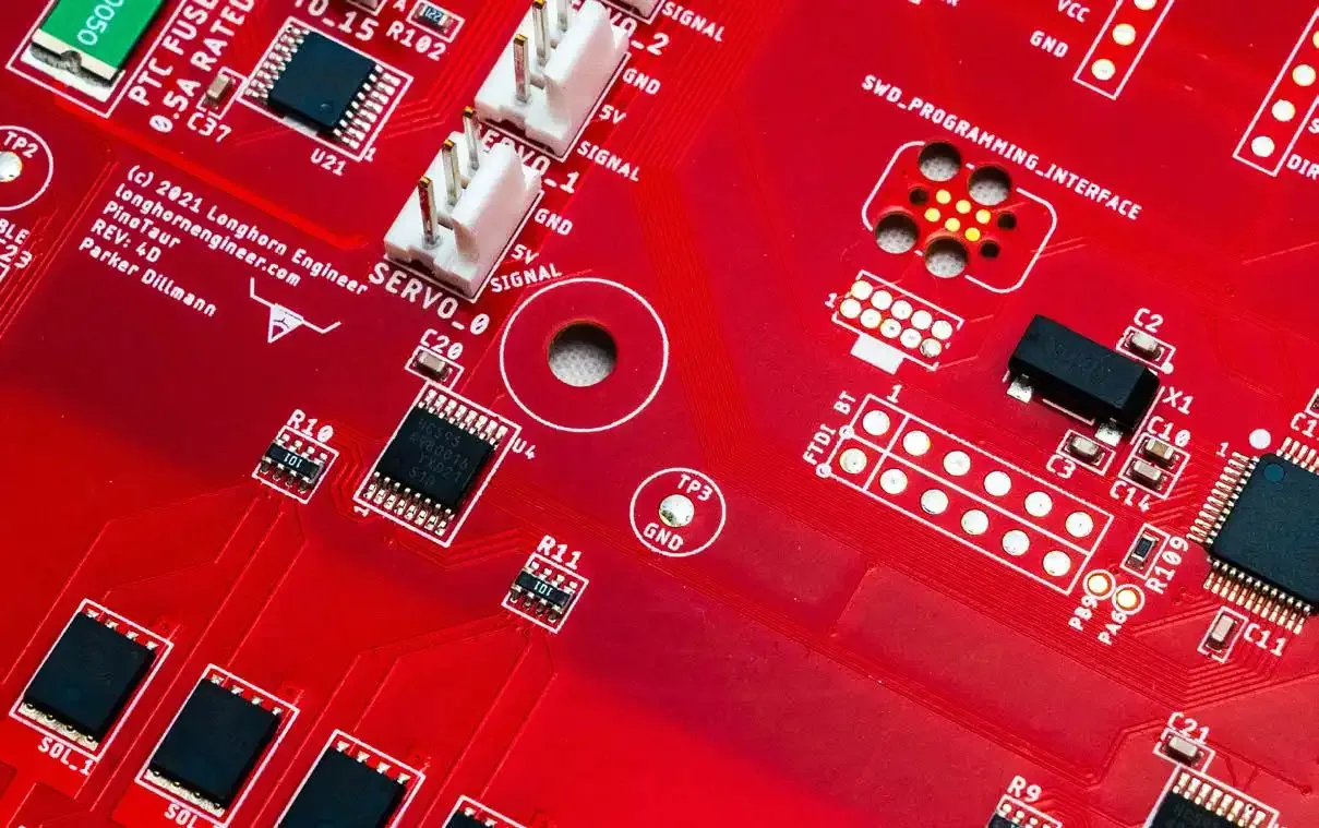
1.1 Debug Headers
Adding debug headers to your PCB assembly prototype provides direct access for debugging interfaces, streamlining troubleshooting and ensuring functionality.
These features are instrumental in diagnosing issues at an early stage and ensuring the prototype’s functionality. Every microcontroller requires its own specific debug hardware and connector part number. Check that there is enough room around the debug connector to ensure clearance to connect and disconnect the typical ribbon cable.
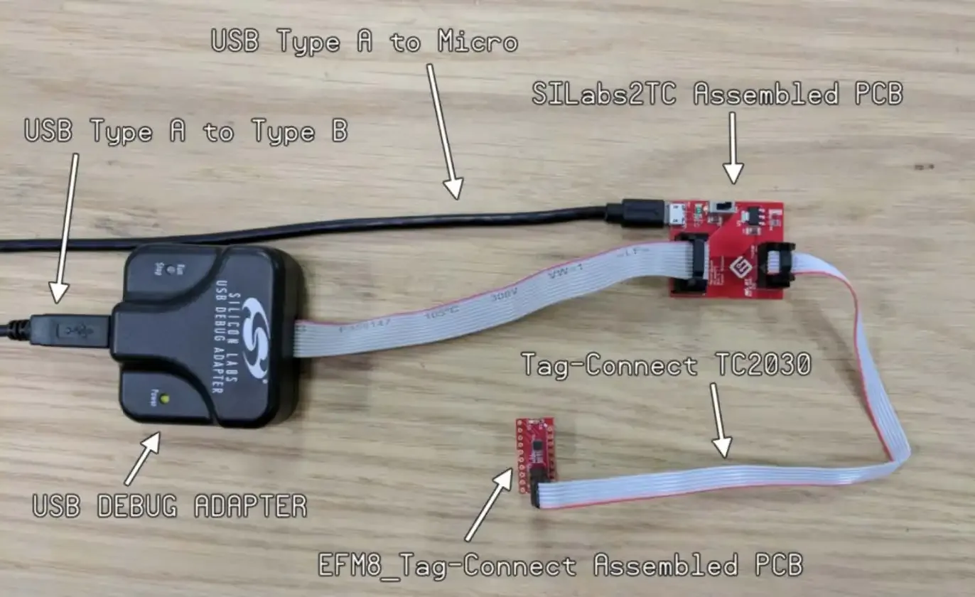
For compact designs, consider the Tag Connect system for its space-efficient, pogo-pin-style connectors. This eliminates the need for bulky traditional connectors. This approach saves valuable board space and simplifies the debugging process, making it more efficient and less intrusive. You may need to develop your own “conversion” boards that adapt your debug hardware to the tag connect cable.
1.2 Heartbeat and Indicator LEDs
Heartbeat LEDs and indicator LEDs are essential debugging tools for microcontroller-based prototypes. These features provide instant visual feedback on system status and performance, reducing the need for external measurement tools. Typically called a “Heartbeat” indicator, this LED can be used as your first “blinky” or “Hello World” that runs on the microcontroller. This LED can be repurposed later to indicate which firmware routines or interrupts are running on the microcontroller.
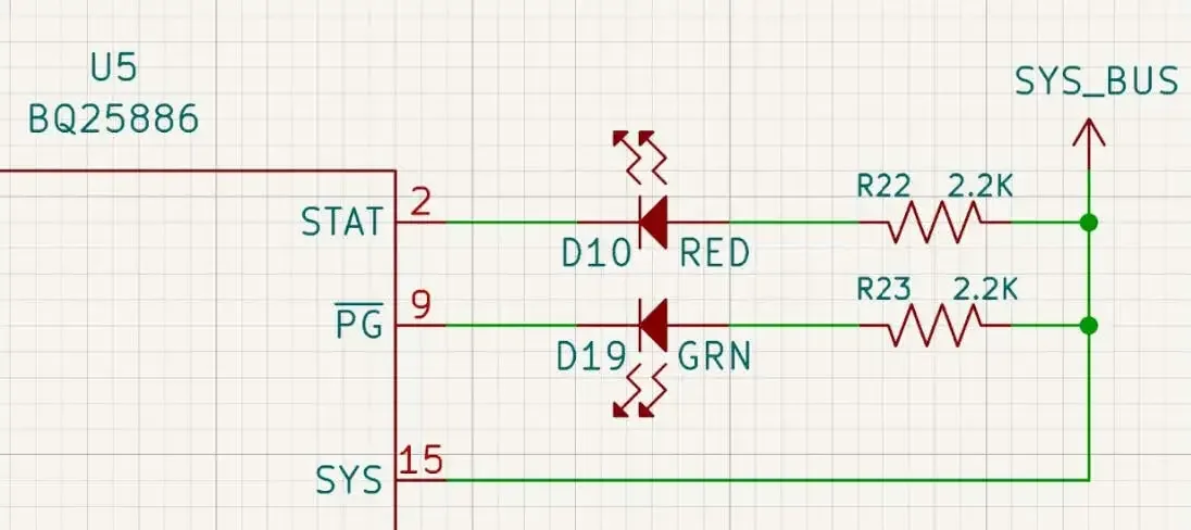
Many active components and ICs have indicator signals like “power good” and “status”. Putting indicator LEDs on these signals makes debugging problems much easier. Instead of having to hook up a meter or logic analyzer you can visually see what is going on.
Similar to the indicator LEDs, putting LEDs on power rails makes for quick recognition if the problem you are trying to solve is power-related or not. For extra credit, have the indicator LEDs go through their own common net connected to a jumper so you can disconnect them to measure system current more accurately.
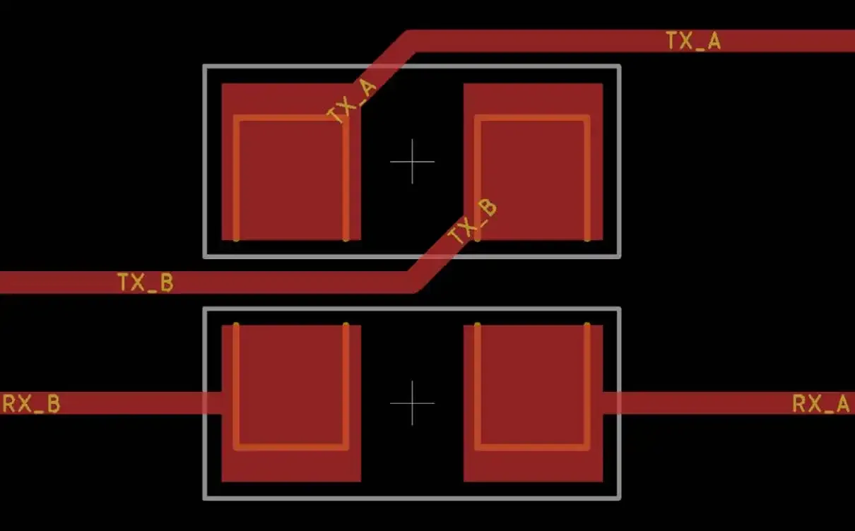
1.3 Swaperoo Resistors
Design your PCB prototype with swaperoo resistors to correct signal errors like reversed UART lines to have flexibility and resilience during testing. Do both chips’ UART lines connect TX -> TX, or is it TX -> RX? The world may never know till you make that prototype. In the unfortunate event that you do cross these two signals, having a way to easily swap the signal connections is useful on prototypes. Putting two zero-ohm resistors next to each other and being able to rotate and cross the signals might save your PCB prototype one day.
Testing Enhancements
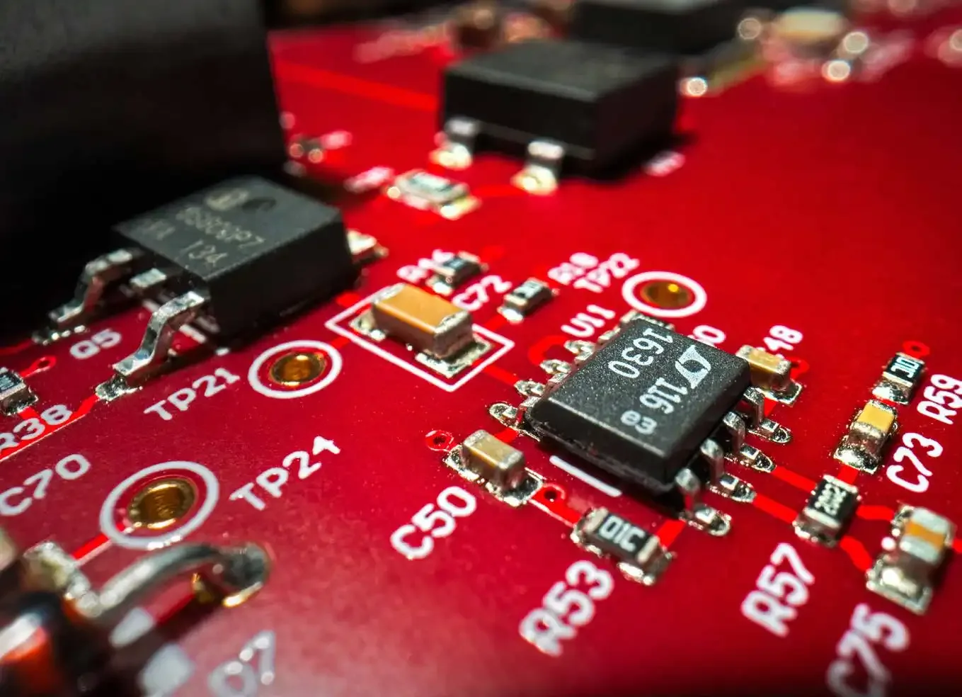
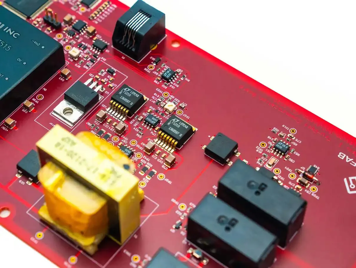
2.1 Test Pads
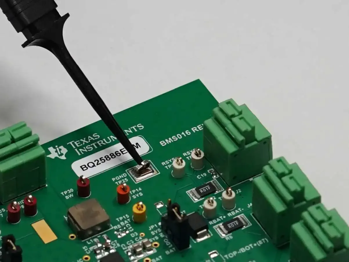
Integrate test pads into your PCB prototype to simplify PCB testing methods and provide accessible points for measuring electrical signals. Integrating test pads into the PCB design early on ensures a smoother transition from prototyping to production by playing a pivotal role in the production testing phase, allowing for thorough checks of circuit functionality in a more automated fashion.
If you have PCB real estate we like to use Keystone 5018 SMT Test points. These unique test points are placed on an SMT pad and feature a ring that allows more secure mounting of test clips. When you move your product to production, this component can just be marked as DNP (do not place) which leaves a test point that an in-circuit tester can easily contact.
2.2 Signal Integrity Probing
Designing PCB prototypes with dedicated points for signal integrity testing is crucial in today’s high-speed electronics landscape. These testing points allow for the assessment of signal integrity, identifying potential issues that could compromise the prototype's performance. Placing additional ground reference points near these critical test points will ensure your test equipment is picking up less noise and you can ensure that the prototype adheres to the required standards for signal quality and reliability.
2.3 Accessibility for Test Equipment
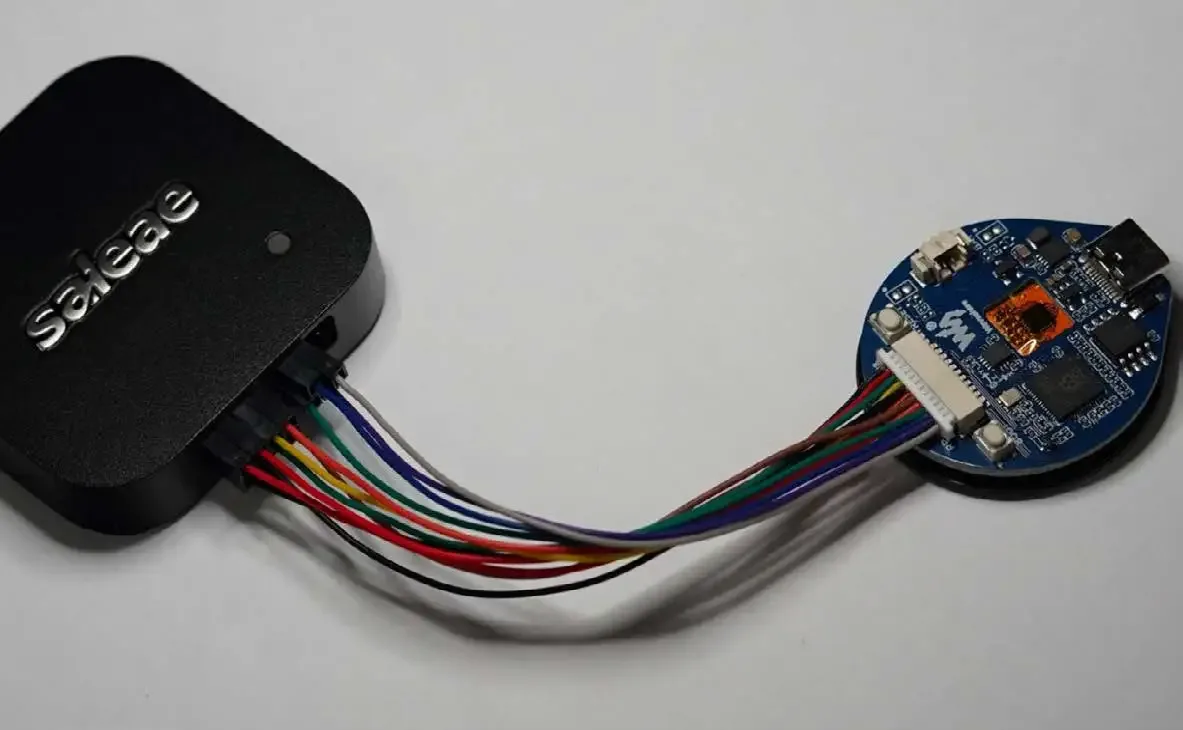
Easy accessibility for test equipment is paramount in PCB prototype design. By designing the board with connectors that seamlessly integrate with test tools, engineers can quickly and efficiently hook up their equipment directly to the PCB. This design consideration speeds up the testing process and reduces the risk of damage and shorting to the board by minimizing the need for makeshift connections.
How many times have you struggled with keeping test clips attached while moving a prototype or having a multimeter test probe slip or unclip itself during a test? Integrate your testing tools and equipment!
2.3 Expose Those Vias
So you have placed test points on every signal you think you may need to probe. Think that is enough? Leave those PCB vias untented and uncovered so they can be used as test points in a pinch. You will thank yourself later.
Want to learn more about testing methods? Read Circuit Board Testing Methods: What You Need to Know now.
Power and Sub System Management
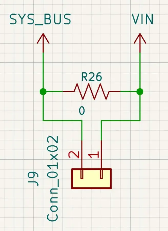
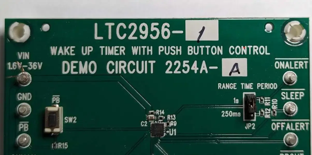
3.1 Jumper Headers on Power Rails
Jumper headers inserted in series on power rails offer a simple solution for power management within the PCB prototype. This feature allows for quick segmentation and troubleshooting of power supplies without necessitating circuit modifications. Engineers can gain flexibility in diagnosing power supply issues and have the ability to measure current draw through each power system.
I like to implement this by having a standard 2-pin 2.54mm header that a shunt can go across. Then in parallel to this header, I like to put a zero ohm resistor. If everything is good with the system I can place a zero ohm resistor and not worry about the through-hole component and shunt.
3.2 Sub-system Segregation
Expand the previous idea to more of your system. Engineers can add the capability to test subsystems individually, significantly enhancing the prototype's diagnostic capabilities. If your new switching power supply is not working you can easily bypass it and use a lab power supply to bring up and validate the rest of the sub-systems. Don’t let a small, non-functioning part of your prototype prevent you from getting more data about your design.
Thermal Management
4.1 Effective Heat Management
Effective thermal management is essential for maintaining the integrity and longevity of PCB components. Including thermal testing points in the prototype design enables engineers to monitor and ensure the board operates within safe temperature conditions. This foresight prevents overheating, thereby protecting components from damage and potentially extending the prototype’s lifespan.
Physical Design Philosophy
5.1 Prioritize Functionality Over Form
When developing PCB prototypes, engineers are advised to prioritize functionality and ease of debugging over form factor considerations. This design philosophy ensures that the prototype is both testable and reliable, and also adaptable to subsequent iterative improvements. Emphasizing debugging and functional validation in the prototype stage lays a solid foundation for a seamless transition to production, ultimately resulting in a high-quality product.
5.2 PCB Mounting Holes
Well-placed and appropriately sized PCB mounting holes are integral to the design of a robust PCB assembly prototype. These elements are pivotal to mounting the PCB physically as well as ensuring its structural stability and electrical safety throughout prototype testing. Having the prototype securely mounted to a base prevents damage to components on the backside when placed or slid around on your bench or desk for testing.
Keep in mind how you are going to use the mounting hole. Make sure to leave enough clearance for the head of the fastener and the tool required. We have a more in-depth article about PCB mounting holes on our blog.
5.3 Utilize All Possibilities
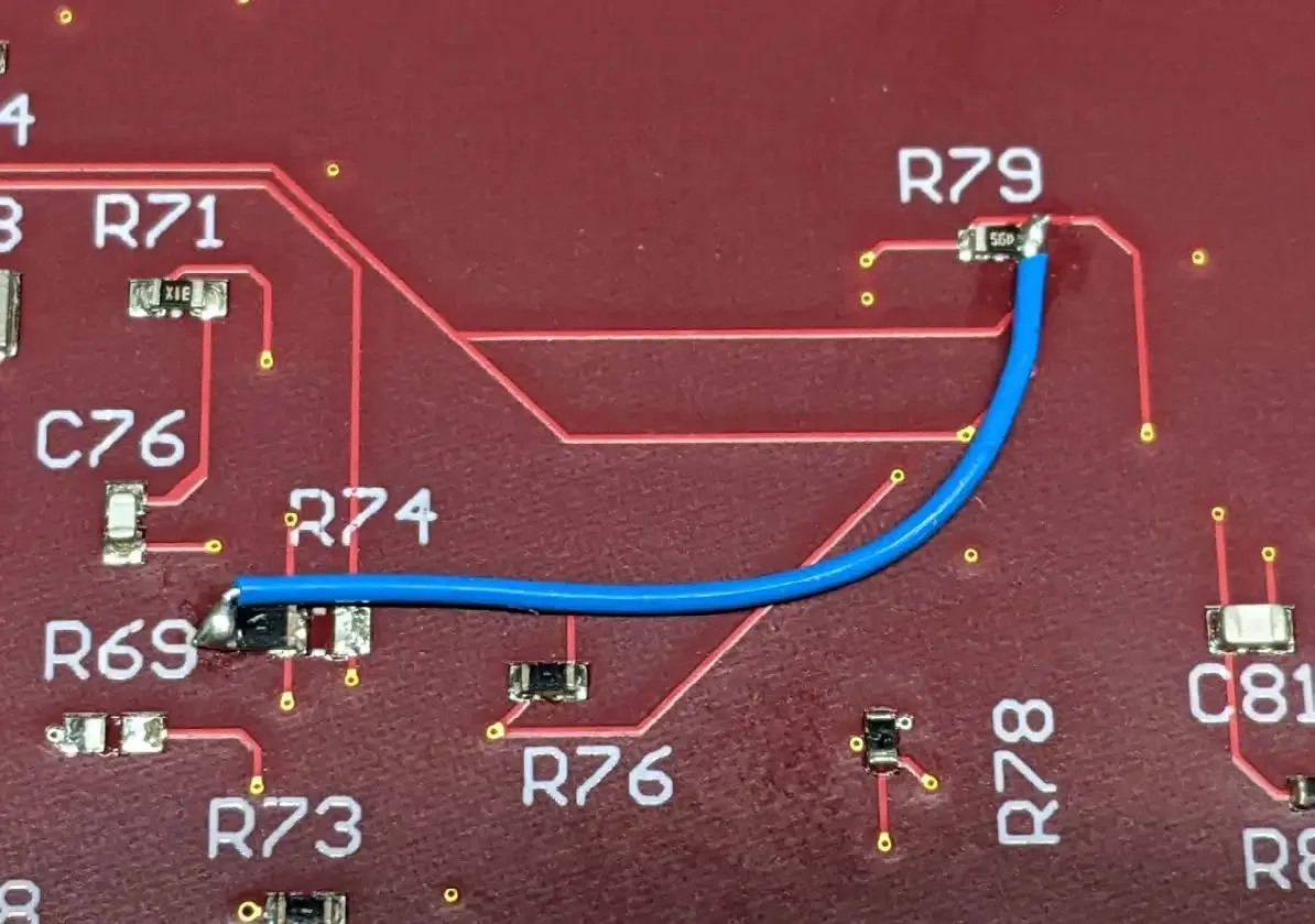
Foresight can be the difference between a straightforward modification and a complete redesign. One such forward-thinking practice involves breaking out unused pins on components and integrated circuits to small test points or headers. This approach maximizes the utility of available board resources and provides an invaluable contingency for future modifications or debugging efforts.
By allocating small, accessible test points for these unused components, engineers ensure they have the flexibility to implement a "greenwire patch" should the need arise. This technique, involving the addition of temporary wire connections to modify circuit behavior, fix issues, or implement new features, can be a lifeline in the development process. It allows for rapid on-the-fly adjustments without the need for re-fabricating the PCB, significantly accelerating development timelines and reducing costs.
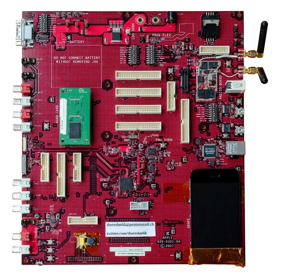
5.4 Meta-Information and Serialization
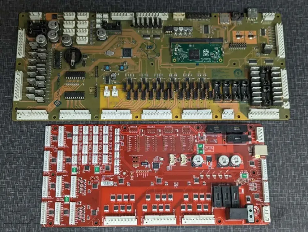
Embedding meta information directly onto the PCB can substantially streamline both the manufacturing process and subsequent troubleshooting phases. Incorporating details like the version number of the PCB and picking a dedicated solder mask color for prototypes versus production directly into the design, as well as encoding hardware identification (ID) with values that your firmware can read, serves as an ingenious method to convey crucial information about the hardware.
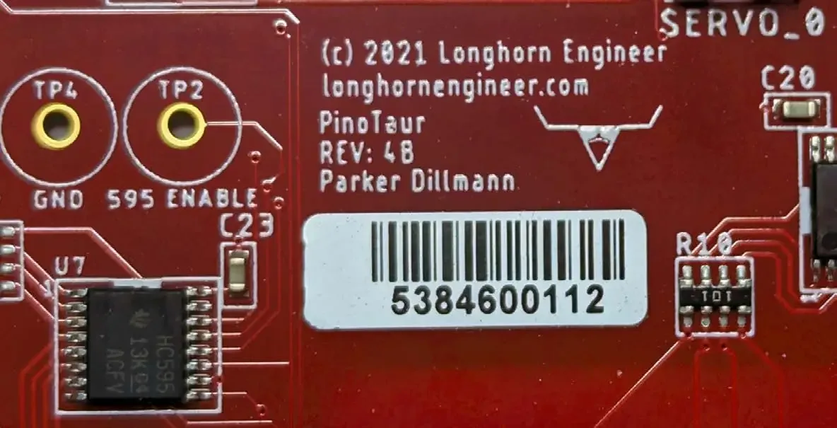
Serialization is not just for production. Having serial numbers on prototypes allows you to closely document modifications, tests, and the lifecycle of your prototypes. Recording your steps in getting your prototype up and running will help you analyze the specific steps that got the PCB operational. If board space is available, leave a 0.5” x 1.0” area for a serialization sticker. The smallest normal PCBA serialization stickers run 0.25”x 0.25” but require more specialized label prints to handle the smaller stickers. Of course, good ole’ sharpie markers work as well!
Checkpoint
Having serial numbers on prototypes allows you to closely document modifications, tests, and the lifecycle of your prototypes.
This practice of embedding meta-information enhances the PCB's self-documenting capabilities, making it easier for engineers and technicians to access essential data, streamline the product lifecycle management, and reduce the potential for errors during assembly or maintenance, thereby embodying a blend of creativity and practicality in PCB design.
Conclusion
Integrating these advanced debugging, testing, and PCB power management features into your next PCB assembly prototype enhances reliability and reduces development time. By focusing on practical design principles and effective testing methods, you can ensure a smooth transition to production. Focusing on debugging features, production testing enhancements, power management, accessibility for test equipment, signal integrity, and thermal management lets engineers address critical aspects of PCB design that influence the prototype’s overall performance and quality, before their PCB fabrication begins.
By prioritizing functionality and designing for easy debugging, you can create cost-effective PCB prototypes that are both innovative and strong enough to handle the realities of the production process. This focus on practicality, from the beginning, will help ensure your design can be built efficiently without needing expensive rework.
Related Topics
MacroFab vs. PCB Manufacturing Brokers: Why Direct Matters
This blog explores the key differences between MacroFab and manufacturing brokers, and why direct manufacturing is the optimal choice for PCBA needs.
Ultimate Guide To PCB Schematics: Concept to Prototype
A comprehensive guide for navigating early design phases and utilizing schematics alongside Gerber and drill files during the PCB creation process.
How MacroFab Uses Clear Communication to Improve Your PCB Production Experience
This blog will discuss how MacroFab can help customers in their PCB production experience through clear communication in a high-octane environment.
Ready to Start Your Next Prototype?
Get an instant quote now!About MacroFab
MacroFab offers comprehensive manufacturing solutions, from your smallest prototyping orders to your largest production needs. Our factory network locations are strategically located across North America, ensuring that we have the flexibility to provide capacity when and where you need it most.
Experience the future of EMS manufacturing with our state-of-the-art technology platform and cutting-edge digital supply chain solutions. At MacroFab, we ensure that your electronics are produced faster, more efficiently, and with fewer logistic problems than ever before.
Take advantage of AI-enabled sourcing opportunities and employ expert teams who are connected through a user-friendly technology platform. Discover how streamlined electronics manufacturing can benefit your business by contacting us today.