The Eagle Part Attribute
Most users of Eagle know how to change the name and the value of a part, but they rarely use the free form part attribute feature. Each part in Eagle has two default attributes; >NAME and >VALUE. Users can add their own attributes using the part attribute function. At MacroFab our Eagle Part Libraries have a MPN (Manufacturing Part Number) and a Populate attribute which is read in by our Eagle ULP script. More info on the MPN and Populate field can be found in our Knowledge Base. This article will show how to add these attributes to a part and how to make these attributes cross over to your PCB for easy silkscreen labeling. If you don’t know how to make a part in Eagle, SparkFun has a really good tutorial on making parts in Eagle.
Adding the Attribute to the Part
To make the attribute display on a schematic symbol, use the text function. Use the greater than symbol “>” followed by what you want the attribute to be named. In this case I chose “Label01” (Figure 1). Notice how the “>NAME” and “>VALUE” attribute use the same format as our attribute. This is because part name and value are default attributes for all parts.
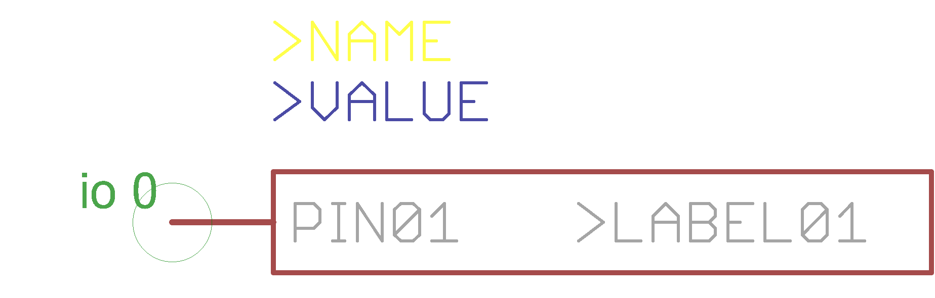
Figure 1 – Eagle Symbol with >LABEL01, >NAME, and >VALUE attribute.
In the footprint of the part, I added the same text to layer 21 tPlace (Figure 2). The next step is to add the attribute to the device, which connects the footprint and the symbol. First, click the blue “Attributes” text shown in the bottom right. Second, click “New” in the Attributes window that pops up, then type in the name of the attribute. In this case, I typed in “LABEL01”. Leave out the greater than “>” symbol. Click OK on both windows (Figure 3).
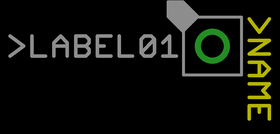
Figure 2 – Eagle Footprint with >LABEL01 and >NAME attributes written with the TEXT function.
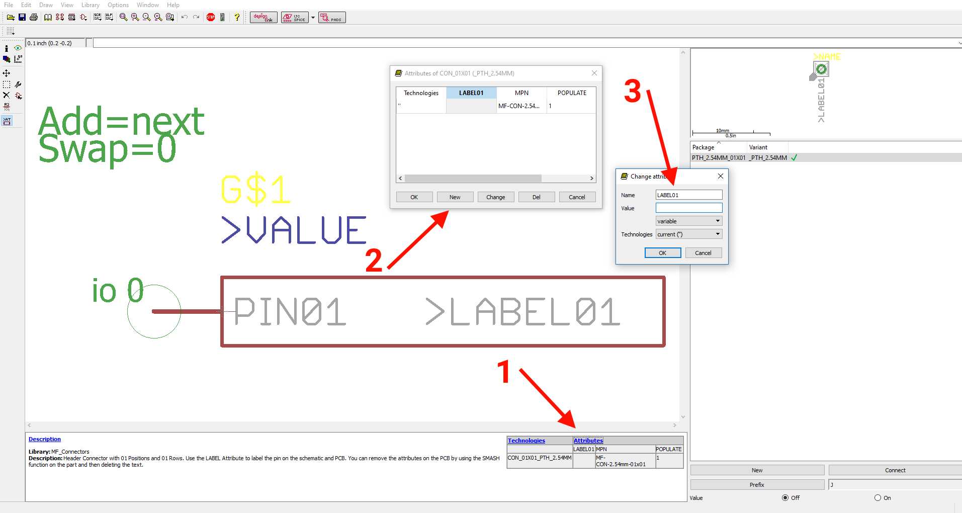
Figure 3 – Eagle device window. This connects the symbol to the footprint and enables the attribute tags added to work.
Using the Attribute in the Schematic and Layout Editor.
Now it’s time to add your part to a schematic. To setup what the schematic text will say, right click the schematic part and click “Attribute” (Figure 4). Find the attribute you want to set and fill in the value (Figure 5). Click OK on the windows and the parts attribute should be filled correctly (Figure 6).
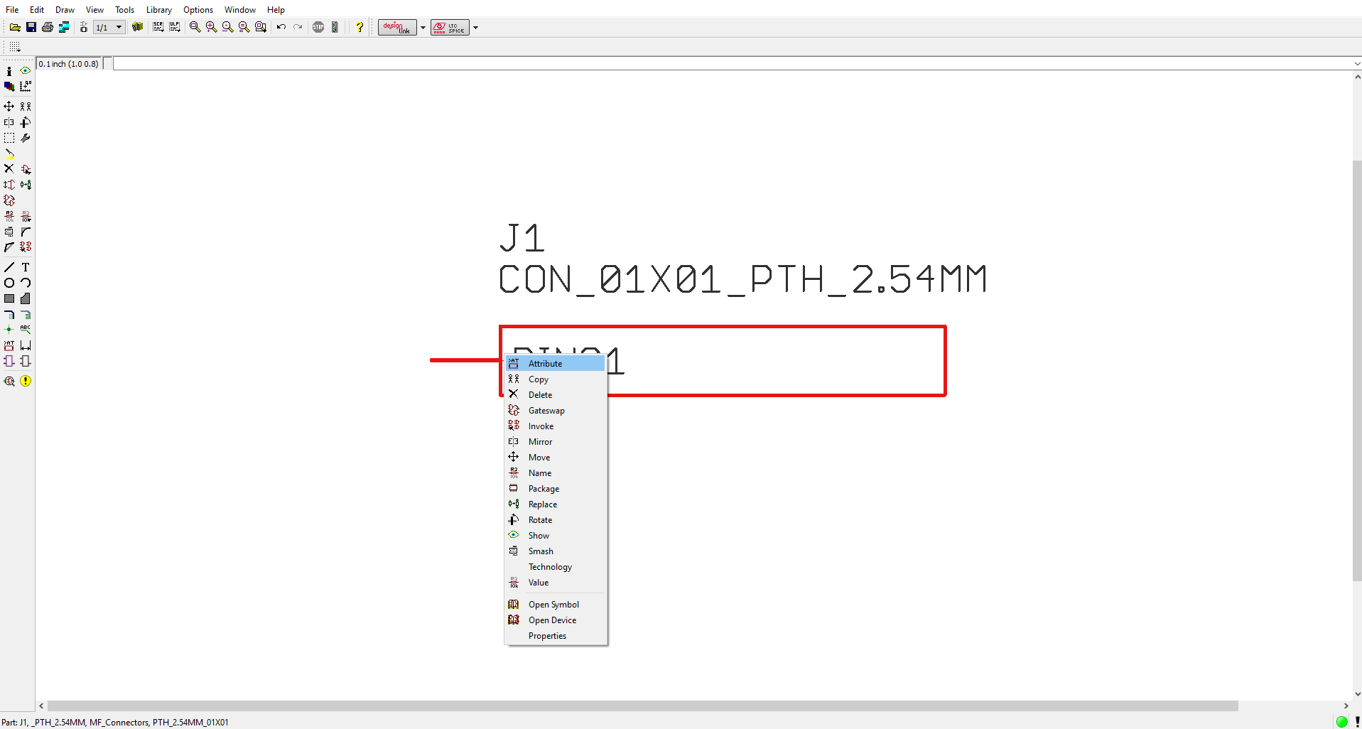
Figure 4 – Adding the value to the attribute in the Schematic Editor.
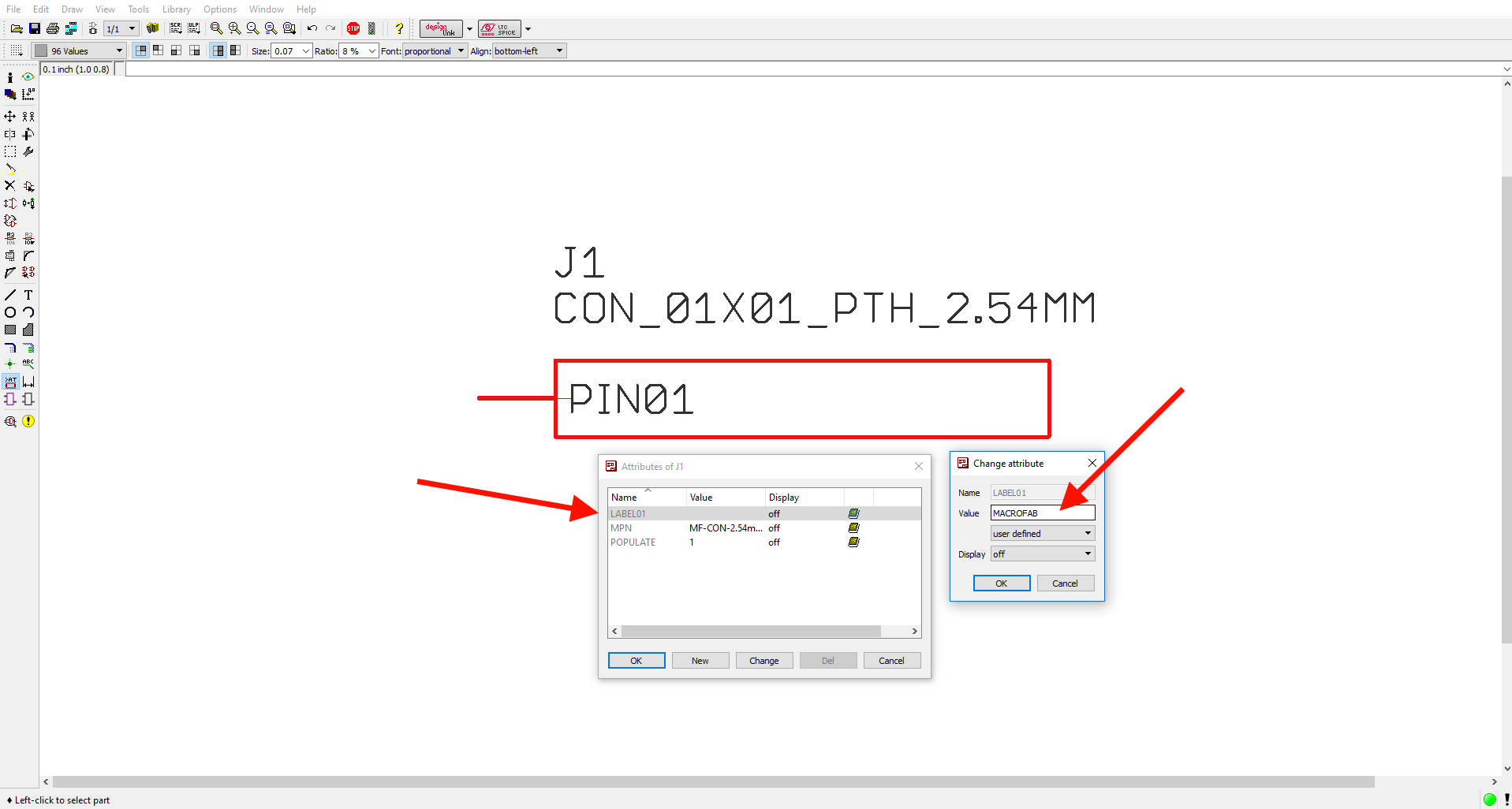
Figure 5 – Continued from Figure 4.
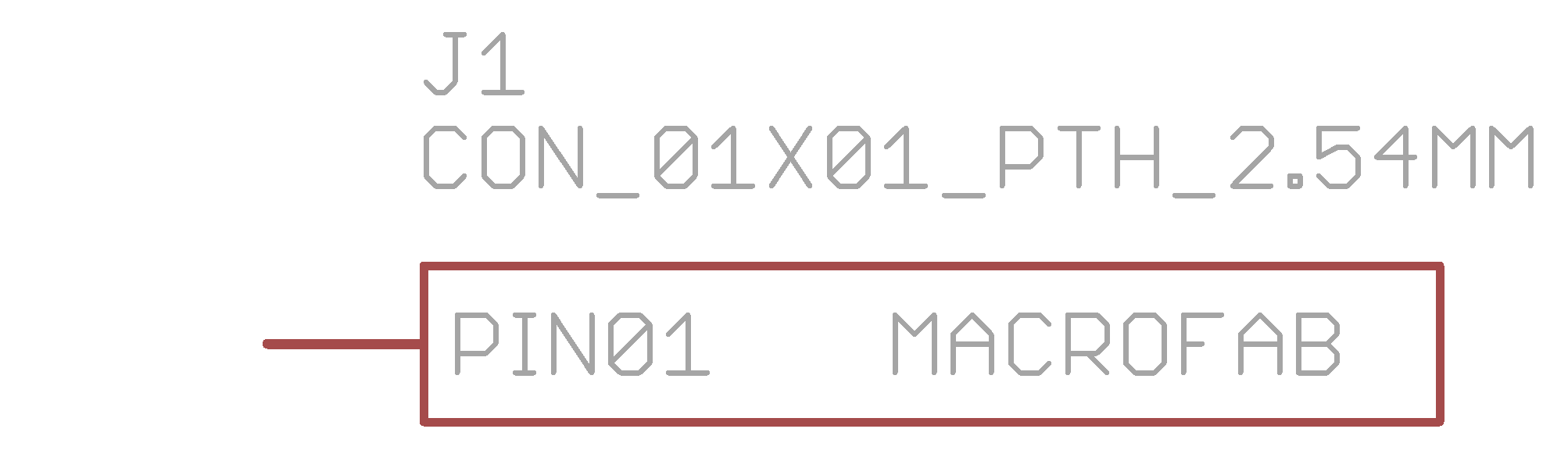
Figure 6 – What the part looks like in the Schematic Editor after the attribute is filled in.
When you switch to the PCB view, the part attribute tag will have also switched to the text established within the schematic (Figure 7). This is useful when setting up pin headers and breakout boards. Figure 8 and Figure 9 show extensive use of this on a larger connector.

Figure 7 – What the part looks like in the Layout Editor after the attribute is filled in.
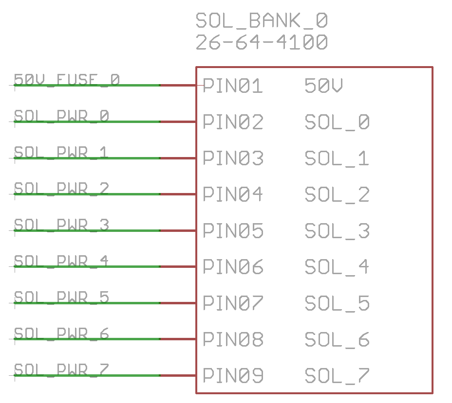
Figure 8 – Larger part using attributes.
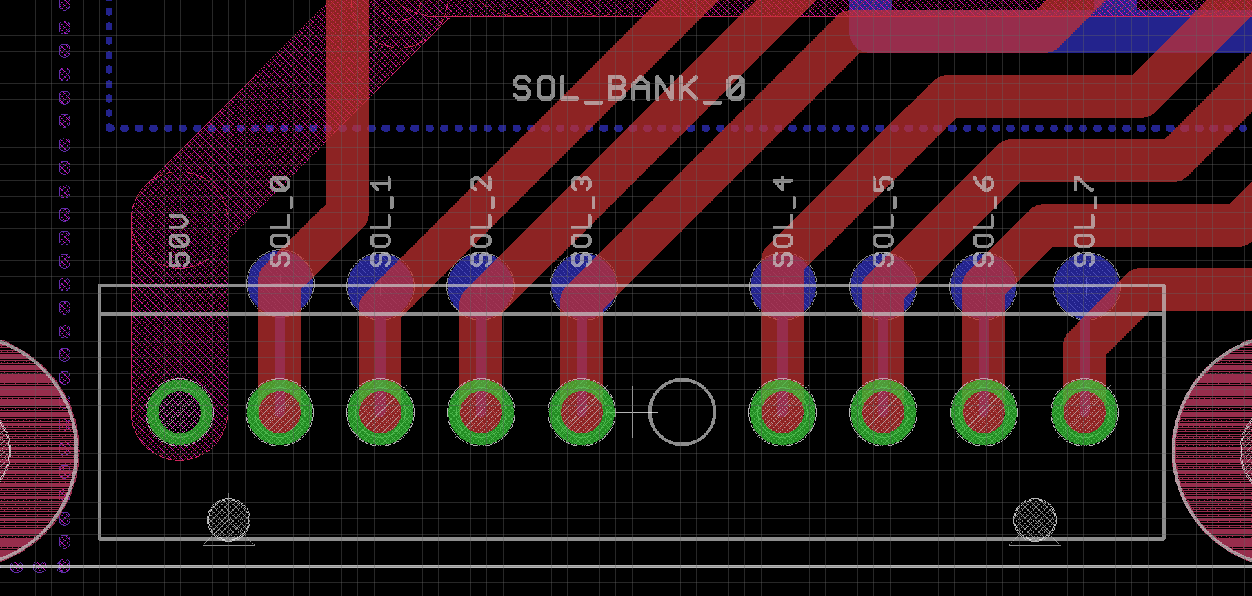
Figure 9 – Larger part using attributes.
Other Examples
At MacroFab, we also use the attribute function in Eagle to add a Manufactures Part Number (MPN) and a POPULATE flag. These are used to specify additional information to the UI and can be found in our Eagle Part Libraries. We also have found this useful in making schematic frames and auto populating designer and board information. See the MF_Aesthetics.lbr library and the image below for a framework we use here at MacroFab (Figure 10).
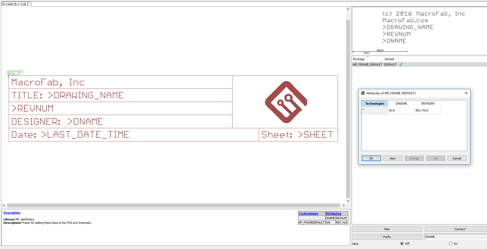
Figure 10 – Another example of using attributes in Eagle.
For more engineering walkthroughs and discussions, check out MacroFab’s Engineering Blog and our weekly Engineering Podcast.