In the last article about the EFM8 series of microcontrollers from Silicon Labs, we talked about designing a simple board with a single LED on it. This time we will get the LED to blink on on the board. This is known as “Blinky” in the maker/hardware world and is similar to the “Hello, World!” program for software engineers.
Simplicity Studio is the software package that Silicon Labs provides to write software for the EFM8 series of microcontrollers. At the time of this article the current version of Simplicity Studio is 4.0.7. Simplicity Studio installs all the drivers you will need for the hardware as well.
Hardware Needed
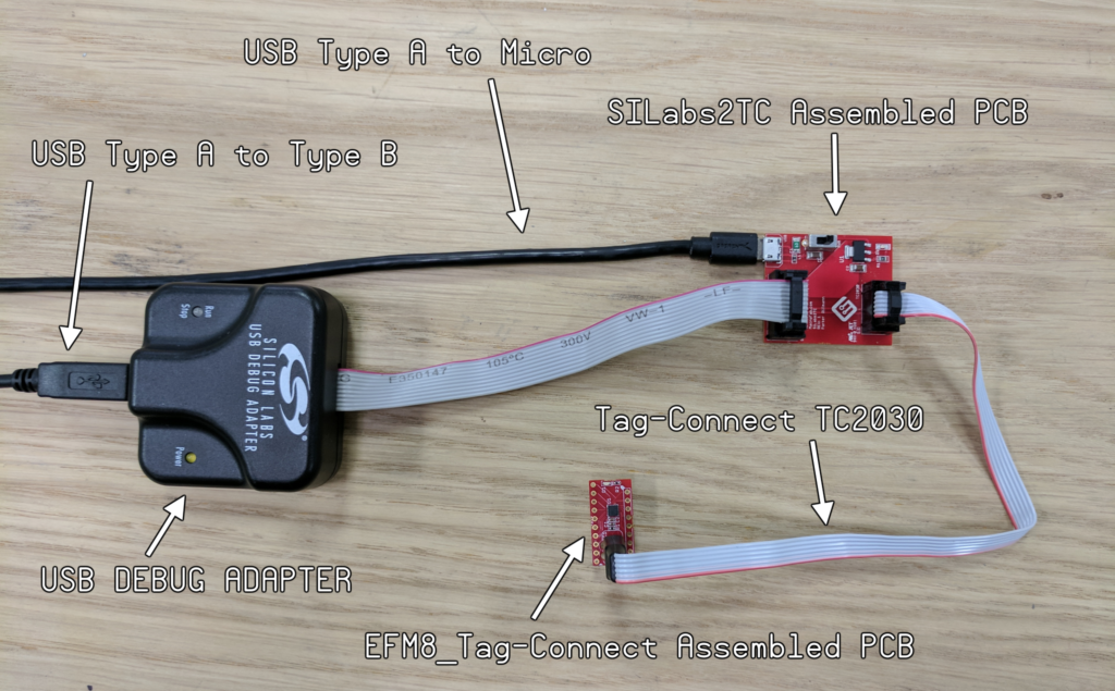
- EFM8_Tag-Connect Assembled PCB
- This PCB is an example board that we will blink the LED on
- All manufacturing files can be found in the MacroFab GitHub Repo
- Check out the article about this PCB.
- SiLabs2TC Assembled PCB
- This PCB is a programming adapter
- Allows the Silicon Labs USB Adapter to connect directly to a Tag Connect cable and supply power
- All manufacturing files can be found in the MacroFab GitHub Repo
- USB Debug Adapter
- Official programmer for the EFM8 ICs
- Allows debugging in the Simplicity Studio IDE
- Part number: DEBUGADPTR1-USB
- Silicon Labs product page
- Mouser currently carries it for $35
- Tag-Connect TC2030
- Connects the SiLabs2TC board to the example board
- Tag-Connect product page
- USB Type A to Type B
- Otherwise known as a USB printer cable
- This cable plugs into the computer to the Silicon Labs USB Debug Adapter
- Amazon Link
- USB Type A to Micro
- This plugs in from a 5V power source like a USB plug on a computer or cellphone charger to the SiLabs2TC board
- Provides power for the Tag-Connect TC2030 cable
- Amazon Link
With everything setup like the picture above, plug the USB cables into the computer you installed Simplicity Studio. The computer should recognize the USB Debug Adapter. If it does not you might have to correct driver for it. Help for this can be found on the Silicon Labs Community Forums.
Software Setup
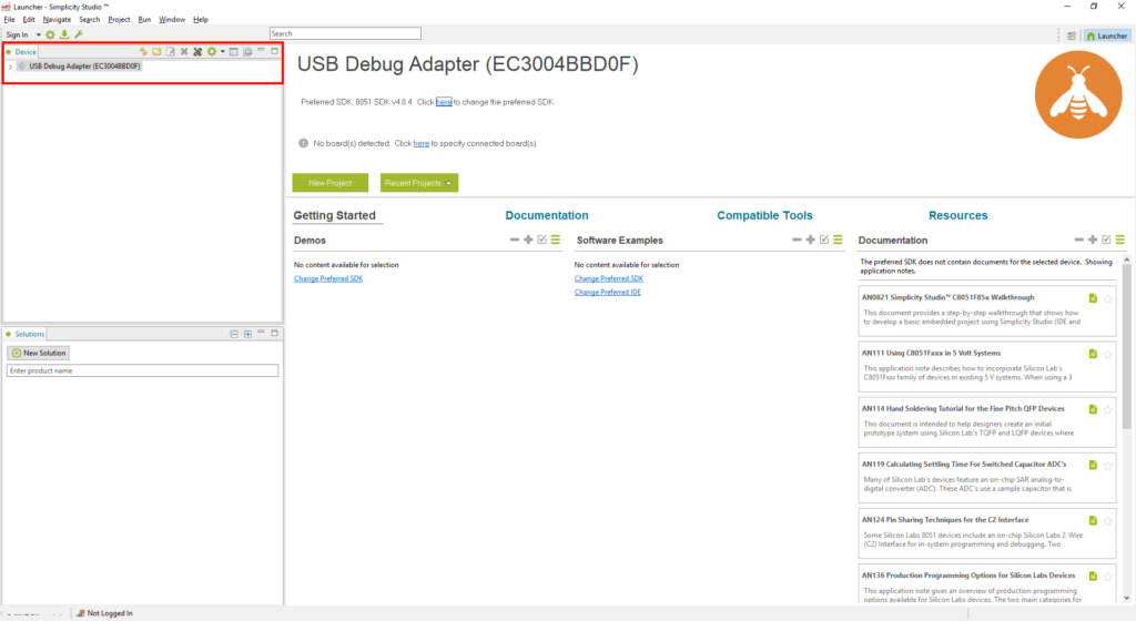
Open up the Simplicity Studio IDE. The first screen is the “Launcher” where you can look at devices, demos, software examples, and documentation. The USB Debug Adapter should be listed in the Device window on the upper right corner.
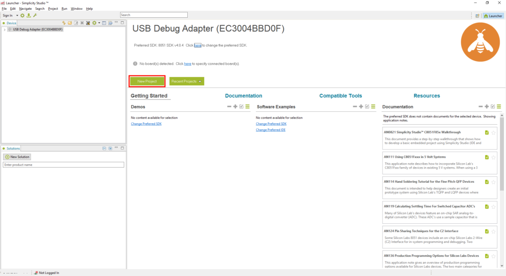
Go ahead and click the green “New Project” button.
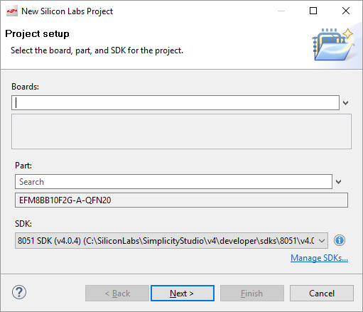
The “New Silicon Labs Project” window should pop up. Leave the “Boards” field empty and in the “Part” area search for “EFM8BB10F2G-A-QFN20” since that is the MCU on the EFM8_Tag-Connect PCB. Under SDK select the latest version. At the time of this article this is 4.0.4. Then click next.
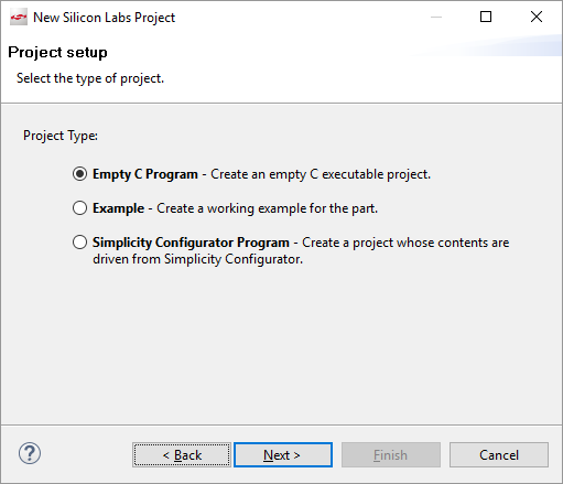
In the next window click on “Empty C Program” and click next.
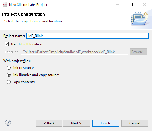
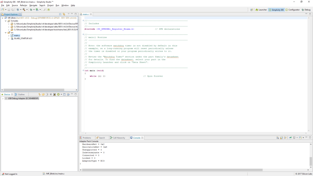
The next window we can name the project. I choose MF_Blink. Click Finish. Simplicity Studio should move from the Launcher tab to the Simplicity IDE tab.
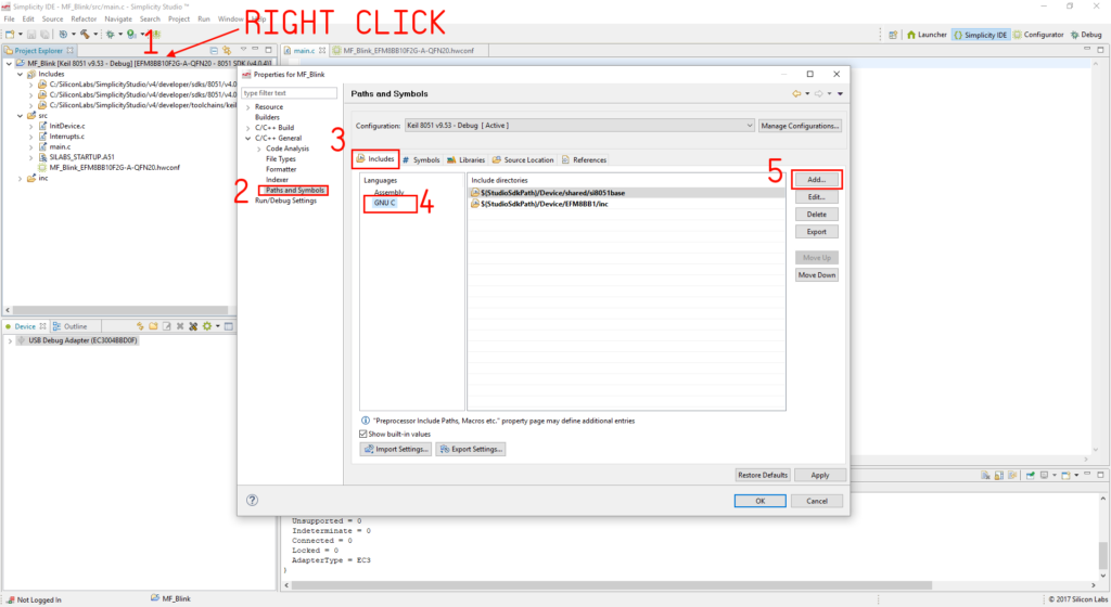
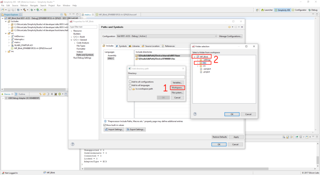
We need to do some house keeping to make sure the compiler knows where our included files are for the project. To do this we need to make sure the “inc” folder is included in the build path for GNU C. Right click on the project in the “Project Explorer”. Navigate to “C/C++ General” then “Paths and Symbols”. Under the “Includes” tab select “GNU C” then click add.
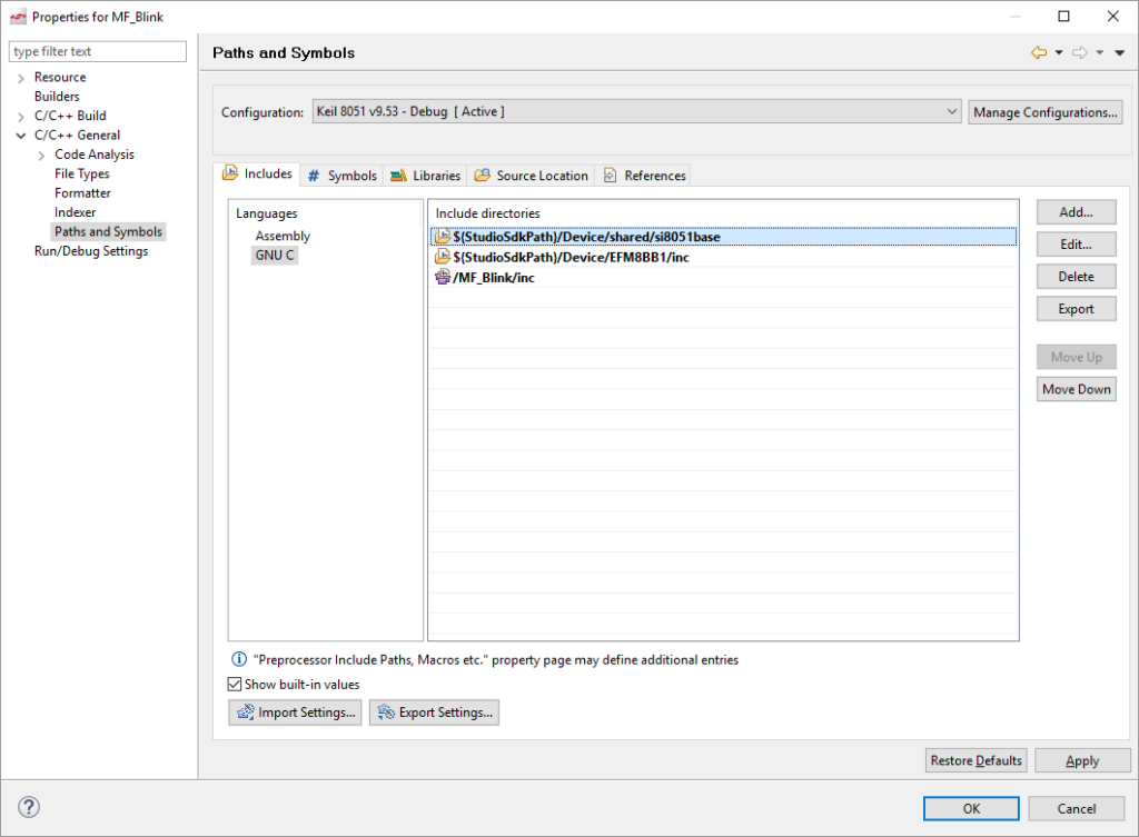
An “Add directory path” window will popup. Click “Workspace…” Then in the next window select the project and the the “inc” folder. Click OK. The “Include directories” should look like the image below. Click OK in the properties window and a dialog box that says “Changes to the include search…” blah blah. Click Yes. I do not know if it is my install but this step to include the /inc folder makes sure the compiler knows that they are there. Without this the IDE will throw missing header errors during the linking phase.
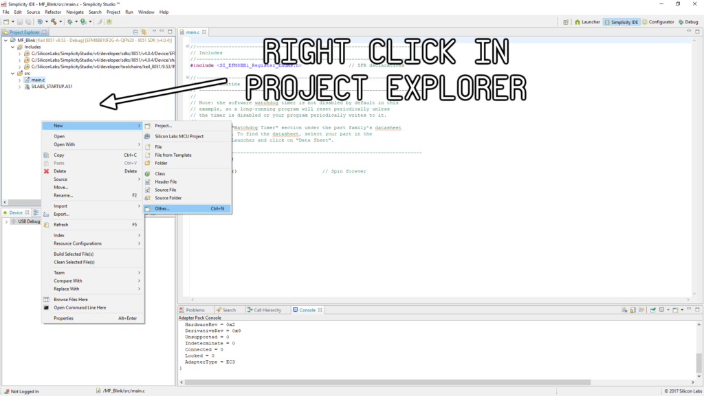
Now our first action on our quest to make this LED blink is to create a Hardware Configuration file! Right click in the Project Explorer which is the window in the upper right of the IDE. Go to New then select Other… Alternatively you can use the keyboard short cut CTRL+N. This will open up what kind of new other file you want to create.
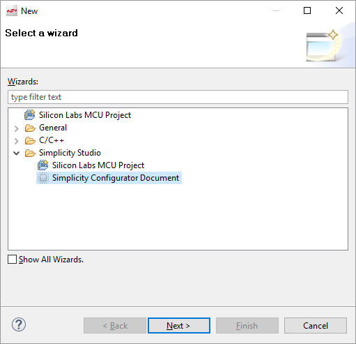
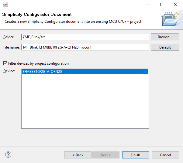
In this window navigate through Simplicity Studio to Simplicity Configurator Document and click next. The next window we do not need to change anything so click Finish.
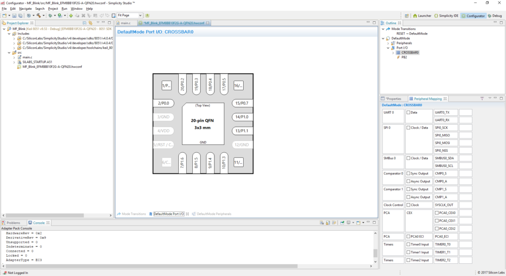
This should open up the Hardware Configurator file which has the extension .hwconf and the Configurator tab in the IDE. The Configurator tab allows configuration of peripherals, clocks, timers, I/O settings and watchdog settings. Inside EFM8 MCUs there is a thing called the Crossbar. The Crossbar enables a peripheral to be connected to different pins and can control if pins are even hooked up to I/O drivers. Let’s enable it first.
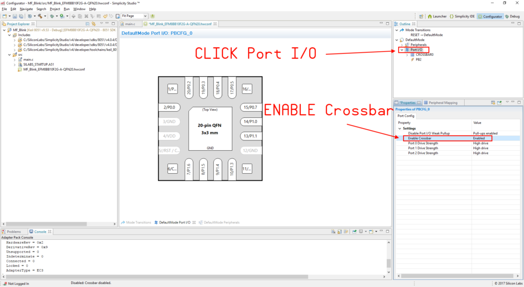
In the upper right side of the IDE there is a window named “Outline”. The Outline window is where you navigate around the Hardware Configurator. Click “Port I/O”. The window below Outline will change to something like “Properties of PBCFG_0”. Then click on “Enable Crossbar” and enable it. If this step is skipped the I/O will not be able to be driven and the LED will not blink.
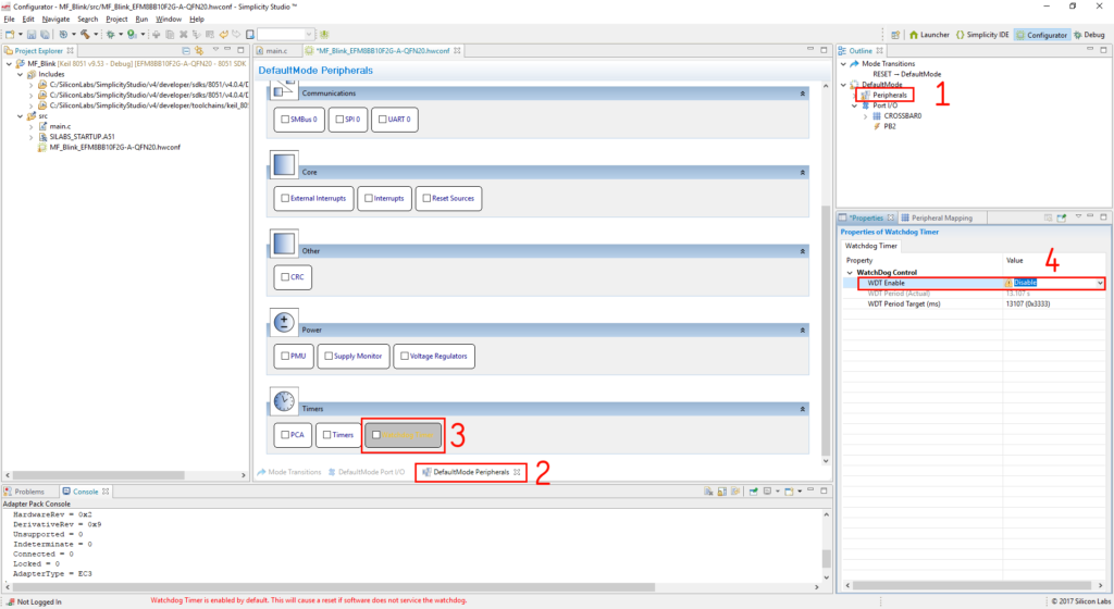
Next step is to disable the Watchdog. The Watchdog is a piece of hardware that checks to make sure the MCU has not crashed or locked up. Since we are just blinking a LED we do not need it. In the Outline window click “Peripherals”. In the center window at the bottom click “DefaultMode Peripherals”. Then scroll down to “Timers” and click on “Watchdog Timer”. In the properties window on the right select the “WDT Enable” and click Disable. Now we can start setting up the rest of the MCU to blink a LED.
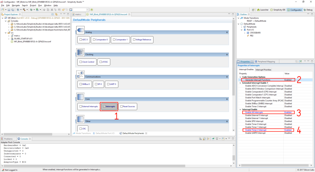
Instead of just counting to a specified number then turning the LED either on or off we are going to use a timer interrupt to do the counting for us. A bit more complicated then a standard Blinky program but this will get us more practice with the Hardware Configurator. Still in the same “DefaultMode Peripherals” scroll up to “Core” and check “Interrupts”. The properties on the right side will change again. Make sure “Generate Interrupt Functions” is enabled. Then under “Interrupt Enable” enable “Enable All Interrupts” and “Enable Timer 2 Interrupt”. This will setup the interrupt function for Timer 2.
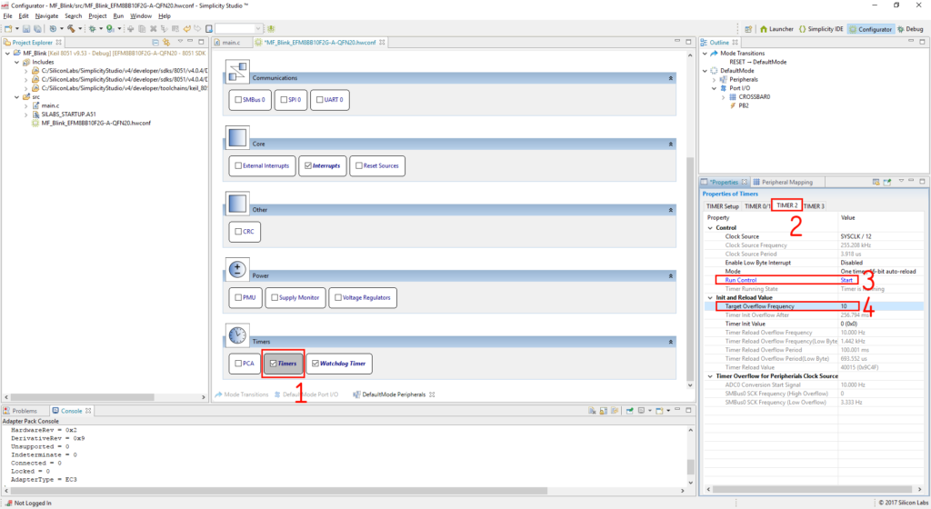
Setting up Timer 2 is next. Scroll down the “DefaultMode Peripherals” and under “Timers” there is “Timers”. Check this box. Properties on the right will change again. Click the “Timer 2” tab. Here we can change all the settings for the timer. Under “Control” turn “Run Control” to “Start”. This will tell the timer to actually count. Under “Init and Reload Value” change the “Target Overflow Frequency” to 10. This will make the timer go off every 1/10 second or 10Hz.
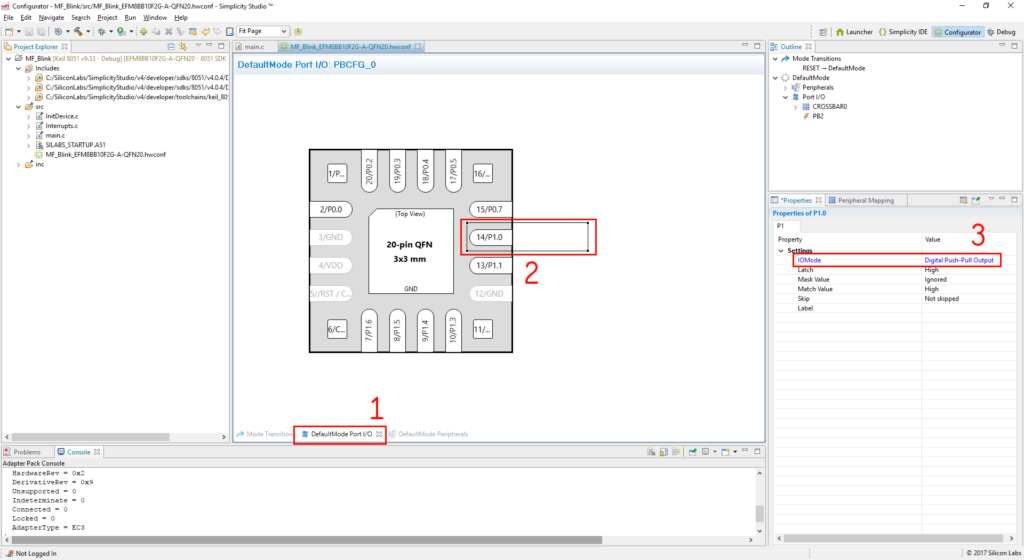
Almost done with the Hardware Configurator! We just need to the the pin that the LED is connected to to an output in the Crossbar settings. On the EFM8_Tag-Connect PCB the LED is connected to P1.0. In the center window click the “DefaultMode Port I/O” tab. This will change the view to what will look like the EFM8 MCU footprint. Click pin 14 which is labeled “14/P1.0”. This will change the property window on the right side. Under settings set the “IOMode” to “Digital Push-Pull Output”. After all that, save the file.
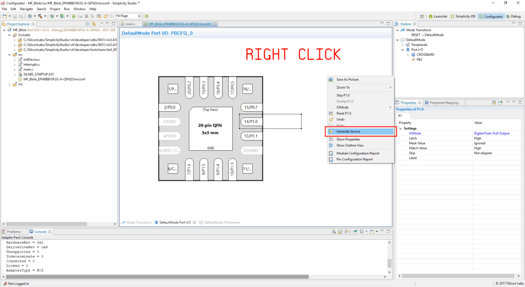
With the Hardware Configurator all setup, right click in the middle window and click “Generate Source”. This will create all the source files needed for the interrupts and timers. Then click the Simplicity IDE tab in the upper right of the IDE so we can start writing the code.
Writing the Code
Open up the “main.c” file. Not a whole lot will be going on here since we are going to run out blinking LED in the Timer2 interrupt but we still need to setup some header files and enable global interrupts.
In the includes section at the top there should already be
#include <SI_EFM8BB1_Register_Enums.h> // SFR declarations Under this, add
#include <InitDevice.h> This header has the Transition Prototypes we need to tell the MCU what to do on reset or power up. There are a couple of other prototypes in the InitDevice.h file for the Watchdog, for other events but we will not need them.
In the main function we need to add the following to the first line of the function.
enter_DefaultMode_from_RESET();
IE_EA = 1; The first line is the Transition Prototype we need and the second line enables global interrupts which will make the Timer2 interrupt actually do something. Our main.c program will look like the following. Save it!
//----------------------------------------------------------------------------- // Includes //----------------------------------------------------------------------------- #include <SI_EFM8BB1_Register_Enums.h> // SFR declarations #include <InitDevice.h>
//----------------------------------------------------------------------------- // main() Routine // ---------------------------------------------------------------------------- int main (void) { enter_DefaultMode_from_RESET();
IE_EA = 1; // Enable global interrupts
while (1) {} // Spin forever } Next open up the Interrupts.c file that the Hardware Configurator auto generated. It will be in the same “src” folder the main.c file was in. The SI_Interrupt routine here is where we will actually blink the LED. To blink the LED every second, a counter will be used to count to 10. This is because we set the Timer2 interrupt to 10Hz. 10 Timer2 interrupts will be 1 second. Easy math! Below is the code.
//========================================================= // src/Interrupts.c: generated by Hardware Configurator // // This file will be regenerated when saving a document. // leave the sections inside the ”$[…]” comment tags alone // or they will be overwritten! //=========================================================
// USER INCLUDES #include <SI_EFM8BB1_Register_Enums.h>
//----------------------------------------------------------------------------- // Global VARIABLES //----------------------------------------------------------------------------- int LEDCOUNT = 0;
//----------------------------------------------------------------------------- // Global CONSTANTS //----------------------------------------------------------------------------- SI_SBIT(LED0, SFR_P1, 0); // P1.0 LED0
//----------------------------------------------------------------------------- // TIMER2_ISR //----------------------------------------------------------------------------- // // TIMER2 ISR Content goes here. Remember to clear flag bits: // TMR2CN0::TF2H (Timer # High Byte Overflow Flag) // TMR2CN0::TF2L (Timer # Low Byte Overflow Flag) // //----------------------------------------------------------------------------- SI_INTERRUPT (TIMER2_ISR, TIMER2_IRQn) { TMR2CN0_TF2H = 0; // Clear Timer2 interrupt flag if(LEDCOUNT == 10) { LED0 = ~LED0; LEDCOUNT = 0; } LEDCOUNT++; } The two sections that are important to note is the following.
SI_SBIT(LED0, SFR_P1, 0); // P1.0 LED0 and
TMR2CN0_TF2H = 0; // Clear Timer2 interrupt flag SI_SBIT is a macro that makes it easy to setup simple pin definitions. The first argument is what you want to call the pin. LED0 since its the only LED on the board is a good name. Second argument is the port it is on. Our pin is P1.0 so port 1. The last argument is which pin on that port. P1.0 is pin 0.
The second is just to clear the Timer2 flag. If the flag is not cleared then the MCU will just jump right back into the Timer2 interrupt. Save the code. It is now time to build!
Stop. Hammer Time!
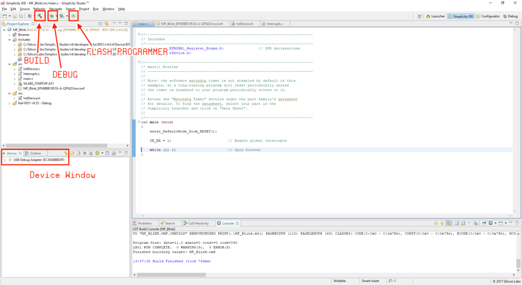
Double check your setup. In the lower left window of the IDE in “Device” the USB Debug Adapter should be there. Click the hammer icon at the top left. This will build the code. If you did everything right it should compile fine. We can push the firmware over to the MCU directly with the “Flash Programmer” that is built in to Simplicity Studio or use the “Debug” functionality. Since this is the first time to push the code we will want to use the “Debug” function. Click the bug that is next to the hammer.
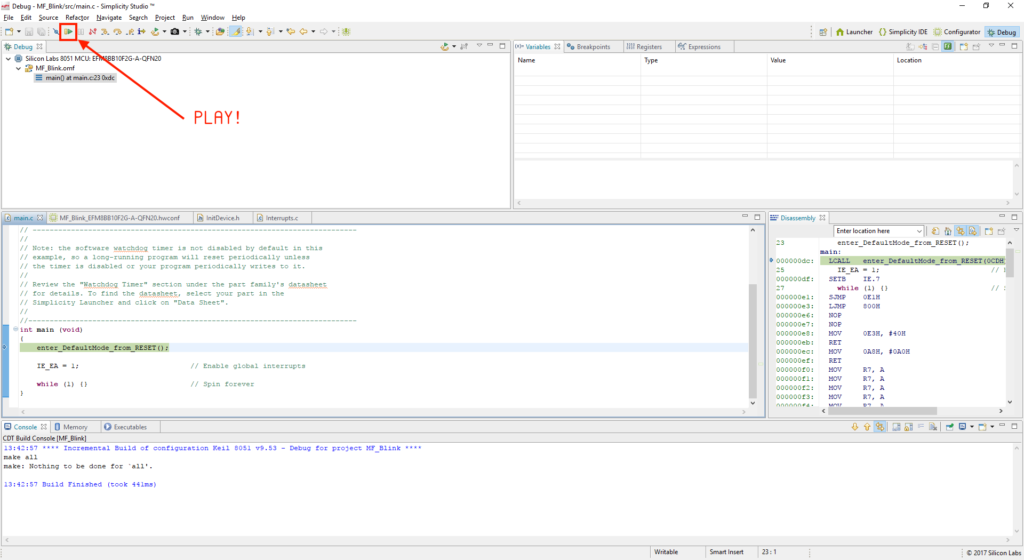
The IDE will build the code again and then upload the firmware to the EFM8_Tag-Connect PCB that is connected to the USB Debug Adapter. The IDE will then move the the Debug tab. Here we can step through the code, look at configuration information, register values, memory location values, and object code. However at this time we are just going to click the “Play” button at the top left. In a later article we will cover how to get the debug functionality working.
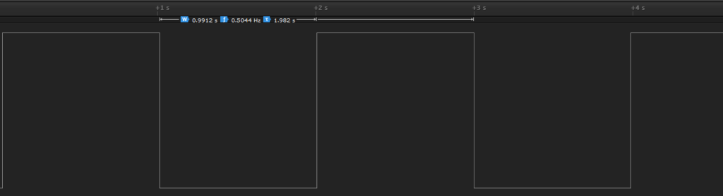
The LED on the PCB should be blinking now!

Then verify the frequency of the blinking LED with a Digital Logic Analyzer. Looks good! We can see how much the internal oscillator drifts by looking at the time here. This is fine for just blinking a LED or simple projects but devices that require communication or strict timing an external crystal will be required.
Recap
The last article and this one should be able to get a EFM8 project up and running with the bare minimal hardware and code. For more examples and inspiration check out the MacroWatch V2 github which is the binary watch that runs off a EFM8 Sleepy Bee. It has sleep mode and uses the Real Time Clock that is built into the MCU. The source files for the EFM8_Tag-Connect board used in this article can be found here. The source code for the Simplicity Studio project MF_Blink is there as well. Next time we are going to explore the debugger!
Was this post helpful? Have other questions? Let us know in the comments below.