Design PCBAs For Power Safety: Dealing with High Voltages
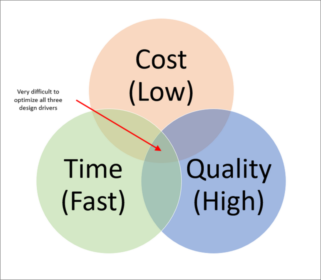
Design for power safety is important. But as companies strive to reduce and or eliminate overhead expenses of product design, engineers will need to develop aggressive design timelines. A constant need to reinvent the internal design process to take advantage of better tools and technology is necessary. However, there is an inverse relationship between design time and cost or quality of the design.

Design For Safety 0
When designing high-volume products, businesses can afford to allocate more resources to the design process, as these costs form a small percentage of the overall manufacturing expenses. However, for low to medium-volume products, the design costs can significantly impact the total project cost. In such scenarios, electronic designers and engineers often aim to expedite the design turnaround by using proven or integrated solutions, which may lead to a compromise on per-unit pricing.
This article focuses on strategies to streamline design time and reduce risk concerning safety in electronic design. The primary areas to concentrate on are:
High Voltage
Energy Limitation
Battery Usage
We will discuss various methods and strategies to enhance your design process with proven techniques while ensuring safety, particularly with high-voltage circuits.

Isolation of High Voltage Circuits
One of the most dangerous parts of the PCBA is the power supply. This is where voltage (often high voltage), is converted to a voltage that is suitable for the electronic design. Most of the time, this involves a buck power supply converting a high AC voltage to a low DC voltage. Designing a safe power supply takes considerable time, failure mode analysis, and expenses related to agency approval.
In addition to the actual safety consideration of the power supply conversion, a switch-mode supply requires designers to put more time and consideration into the PCBA layout to mitigate switching noise in the layout. However, there are millions of class II power supplies sold globally each year for use in laptop computers, cell phones, and a variety of other devices.
Why not take advantage of the volume and existing designs available and simply use an off-board, commercially available, class II power supply and simplify the PCBA design? In this manner, we avoid many of the safety considerations, not to mention noise considerations, of an “on board” high voltage switch mode power supply. In many cases you will find purchasing a high volume commercially available power adapter will prove cost-effective.
High Voltage Switching
Even if we opt to purchase an off-board power supply, we may still need to address switching high voltage on the PCBA. Switching high voltage on and off is simpler than converting to it, however. When PCB traces of differing voltages are routed too close together a phenomenon known as arc tracking can occur.
There are numerous guidelines for creepage distances on PCBs depending on voltage. The higher the voltage, the higher the required creepage distance.
Arc tracking is caused by contaminants on the PCB creating a short circuit path between traces. This can cause a resistive short that can heat up and potentially ignite. While maintaining minimum creepage distances should be a goal for every design, this might be challenging, time-consuming, or impractical in some situations due to space constraints.
Do you work in the energy sector? Read The Next-Gen Power Grid: Designing Systems for the Future to learn how PCBA design will impact tomorrow's energy grid.

Design For Safety 2
Maintain Isolation
When switching high voltage, be sure to use appropriately rated optical couplers or relays. These devices are constructed in a manner that respects minimum creepage distances for their rated voltage. It is best practice for AC voltage to just switch the line or “hot” and not bring the neutral onto the PCBA. However, it is necessary to bring both the positive and negative sides of a high-voltage circuit on the PCB.
Always keep the high voltage side of the PCB separated from the low voltage side of the PCB. Many designs will even have a silkscreen line between the two sides for clarity. If possible, route the positive and negative sides of the high voltage on opposite sides of the PCB. This is a cost-effective manner to maintain creepage distances.
Another cost-effective method is to cut a slot between the low-voltage side of the PCB and the high-voltage side. Slots can also be cut between the high-voltage traces (of differing polarities). The creepage distances for voltages in the air are much less than creepage distances on a surface.
Additional arc tracking protection can be achieved by applying a conformal coating to the PCB. The conformal coating provides an additional layer of insulation and reduces the occurrence of contaminants from meeting conductive surfaces. Creepage distances can be reduced when an appropriate coating is applied.
Finally, for severe environments where excessive dust, water, humidity, or other particles are present, consider potting the entire PCB assembly. While PCB potting is the most expensive of the options, it is also the most reliable method of sealing the PCB and preventing many hazardous conditions.
Energy Considerations and Fuses
While low voltage is considered safer than high voltage, there continues to be a concern over the energy available. While a class II power supply is an energy-limited device, there are many applications where the PCB might run directly from a battery.
Anyone who has made the mistake of removing the positive cable of a car battery, before removing the negative cable, and accidentally touched the tool to the surrounding metal can appreciate why it is desirable to energy limit the power to our PCB.
For this reason, it is recommended that the PCB be designed with an intentional “weak” spot in the incoming power circuit. This can be most easily accomplished by placing a fuse in line with a power line. PCB-mounted fuses can be purchased and incorporated in many different layout options (SMD or through-hole). The advantage of the fuse is predictable behavior. There are also resettable PTC fuses and active component devices that perform current limiting.
Design for Power Safety: Batteries
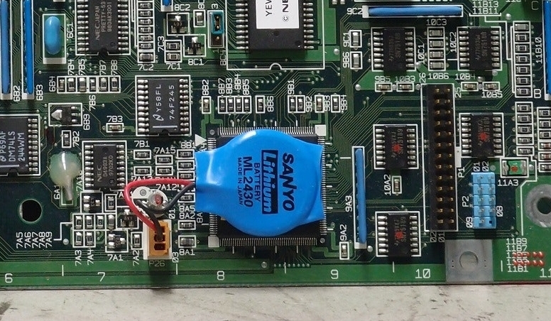
A final consideration for safety is if your product incorporates batteries and recharging circuits into the design. Lithium and lithium polymer battery technology available has given engineers the ability to have a very high watt density in much smaller packages. However, these batteries and charging circuits when designed or used improperly can lead to safety concerns.
If using a battery (particularly lithium) it is recommended to use a battery that has internal protection against short circuits, overvoltage, overcharging, and overheating. While these batteries may cost more, they mitigate much of the design risk when timelines (and design volumes) are a concern.
In addition to using batteries with internal protection, there are a variety of charge management ICs available with excellent application notes, schematics, layouts, and even test PCBAs that can be incorporated into your design. It is well worth the time to use these resources.
Hopefully, the advice in this article will assist you during your next “budget-constrained” or “aggressive timeline” project. They should allow you to reduce your design time while being confident that you have not compromised the safety of your design.
About MacroFab
MacroFab offers comprehensive manufacturing solutions, from your smallest prototyping orders to your largest production needs. Our factory network locations are strategically located across North America, ensuring that we have the flexibility to provide capacity when and where you need it most.
Experience the future of EMS manufacturing with our state-of-the-art technology platform and cutting-edge digital supply chain solutions. At MacroFab, we ensure that your electronics are produced faster, more efficiently, and with fewer logistic problems than ever before.
Take advantage of AI-enabled sourcing opportunities and employ expert teams who are connected through a user-friendly technology platform. Discover how streamlined electronics manufacturing can benefit your business by contacting us today.