To ensure that elements from different PCBs do not interfere with each other during our batching, panelizing, and manufacturing process, the MacroFab platform automatically removes elements from a PCB layer which lies outside of the board outline.
For some layers, this is not a serious problem. Silkscreen or solder-mask features which are outside of the border do not normally have an impact on the final result. For other layers such as copper and drills, this may result in your board not being manufactured as you expect. The platform provides an warning to you in the PCB Design Viewer indicating that we have cropped features from your board which were outside of the board outline.
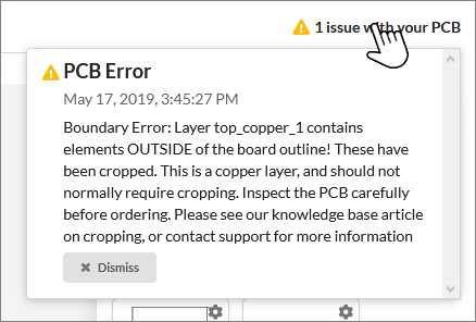
In any case where you see a message that elements are cropped, the board should be examined very carefully before ordering. If you have any questions about why your specific board has elements that have been cropped, please contact support.
Common Cropped Drill Errors
In the case of drills, this is almost always an issue that needs to be addressed before you order the board. The following are issues that can cause cropping of drills.
Incorrect Origin for Drill files
The drill file must use the same point for the origin as the Gerber files for the other layers. Failure to do so will result in drills not lining up with other features in your board, and drills getting cropped.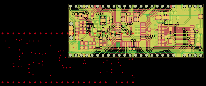
Here we have a case where the Gerbers are using the lower left-hand corner of the board as the origin, while the drill file is using the center of the board as the origin. The will result in a number of the drills being cropped, as well as the remaining drills being in the wrong location. The fix for this is again to check your export settings for the drill file when exporting the drill file from your EDA tool. You can also use a Gerber manipulation software like GerbV to move the offset of the drill files.
Incorrect Number of Digits in the Drill File
The specifications for the Excellon file allow flexibility of the precision of the coordinates of the drill locations. The standard format for Excellon drill files is 2:4 LZ INCH. The 2:4 calls out how many digits the drill location can have. The first number (2 in this case) calls for two digits for the integer portion of the location and the second number (4 in this case) calls for four digits in the decimal portion. LZ stands for Leading Zero Supression. This means the leading zeros of the drill location are removed. INCH calls out that the drill hits are in imperial inch format.
The MacroFab platform supports many different formats. Most EDA tools produce the Excellon drill file with a header that calls out what format the file is in. There are some EDA tools that do not use a header in the Excellon drill file which can cause problems.

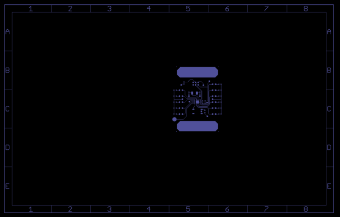
Here we have used the Zoom to Fit feature of Gerbv to show all of the features that have been loaded. Because the drill file does not have a header to tell GerbV what format it is the coordinates of the drills are all off by a factor of 10, placing all the drills outside of the board outline. They will all be cropped when uploaded to MacroFab. To correct this, check your EDA tool for an option to set the Excellon drill file format to 2:4 LZ INCH or use GerbV to change the file format and export as a new Excellon drill file. GerbV will write in the header information.
Common Cropped Copper Errors
In the case of copper layers, this is often an issue that needs addressing. There are exceptions, however where the cropping will still produce a board that will be what you expect. Common issues that cause cropping of copper layers are:
Title Blocks
Some EDA tools include a title block on every layer (including copper layers) which lie outside the board outline. Ideally, when exporting the gerbers from your EDA tool, you should indicate that the title block should not be included. However, if they are included on your copper layers, they will be cropped, resulting in the error message. If the only elements that have been cropped are title blocks or other documentation outside of the outline, then the board may be ordered without issues.
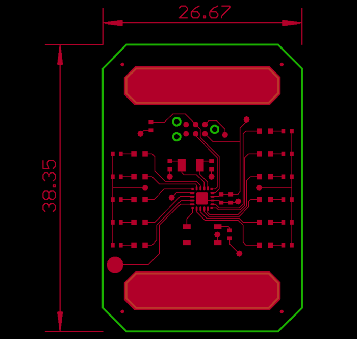
Alignment Marks and Dimension Lines
These marks are generally put on every layer to aid in the alignment of the layers and masks in the manufacturing of the PCB. However, the MacroFab platform does not require alignment marks. Make sure your files do not have alignment marks and dimension lines. These can usually be easily removed using GerbV.
Still have PCB Cropping Questions?
If you still have PCB layer cropping problems or have more questions, let our support team know! We will take a look at your PCB files, find the problem, and get your PCB project up and running!