MacroFab Blog
In the last SSPS design blog post, we discussed using the OPA541 high-powered opamp in the output section of the SSPS. Here's the datasheet for the opamp.
Thermal Design
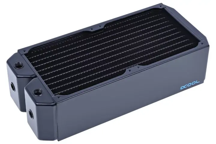
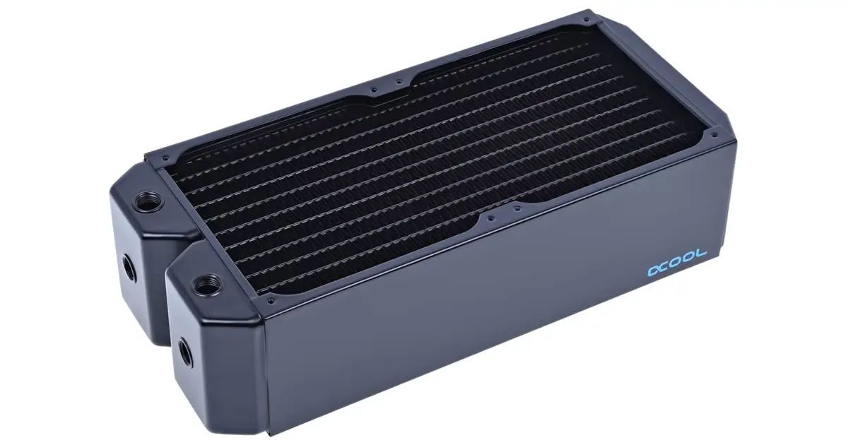
Figure 1: Radiator
Since we will be using the OPA541AP model the voltage supply rails are limited to a maximum of +/- 35V (on the OPA541BM/SM models the rails are +/- 40V) and the goal was to have a full 10 amp output current capability. Being able to supply that much power to a load can result in significant heat buildup in the opamp.
Dissipating large amounts of heat is not a trivial task and can get expensive quickly. Finding the right heatsink and fan to match all of the design requirements is not simple and for our design, an off the shelf solution may not even exist. After considering the design difficulties of using a forced air method of cooling our output opamps, we decided to go with a water cooling system.
Water cooling has a lot of benefits over forced air when considering our power supply application. First, water cooling is significantly more efficient in terms of dissipating watts per square inch. Second, water cooling allows us to deliver our cooling liquid directly to the components that need the cooling most, which allows us to have our cooling area smaller.
Our cooling system consists of a copper block on which we will mount the opamps (and all other heat generating components such as rectifiers and any pass transistors) along with a radiator and a pump to cycle the water. The radiator will be mounted with two 140mm fans.
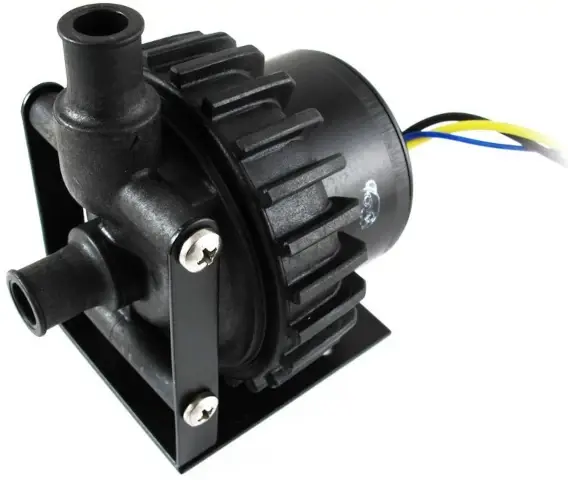
Figure 2: Water Pump
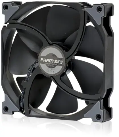
Figure 3: 140mm fans
Power Supply for the Power Supply
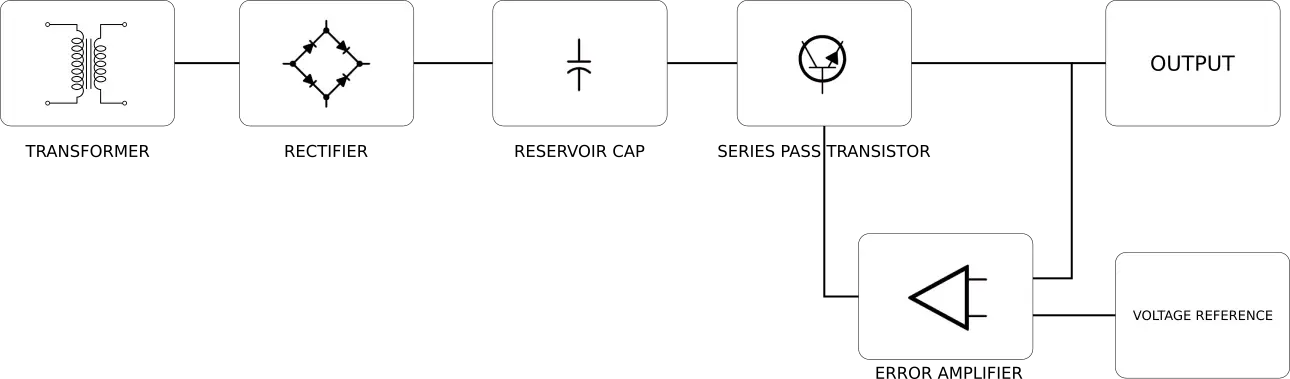
Figure 4: linear regulated power supply block diagram
The output section of the power supply needs clean DC rails at +/-35 volts. Typically designing a dc power supply to provide this kind of voltage is fairly easy but with our 10A output requirement we will need to be careful with our component choices and layout. 350 Watts (35 volts times 10 amps) is not a small amount of power and poor design could cause big problems with a lot of smoke.
To create the +/-35V power supply rails we opted to use a tried and true regulated linear pass transistor configuration.
Here is a block diagram of the regulated power supply:
The first block in the diagram is the transformer which is arguably the most important component in the power supply since it will be taking the mains line power and converting it to something useful for us. All of the power for the entire power supply will pass through this transformer so it must be chosen carefully.
We opted to go with a toroidal type transformer since they are more compact, more efficient, and potentially less noisy. The transformer we selected for our application is the Antek AN-8430. This transformer has a hefty 800VA rating and can handle 20% overloads without issues.
This transformer has output taps rated at 30V RMS or 42V peak which would need to be regulated down to our required +/-35V. Knowing the peak output voltage our transformer provides gives us a starting point for the rest of the power supply design.
Schematic and Simulation
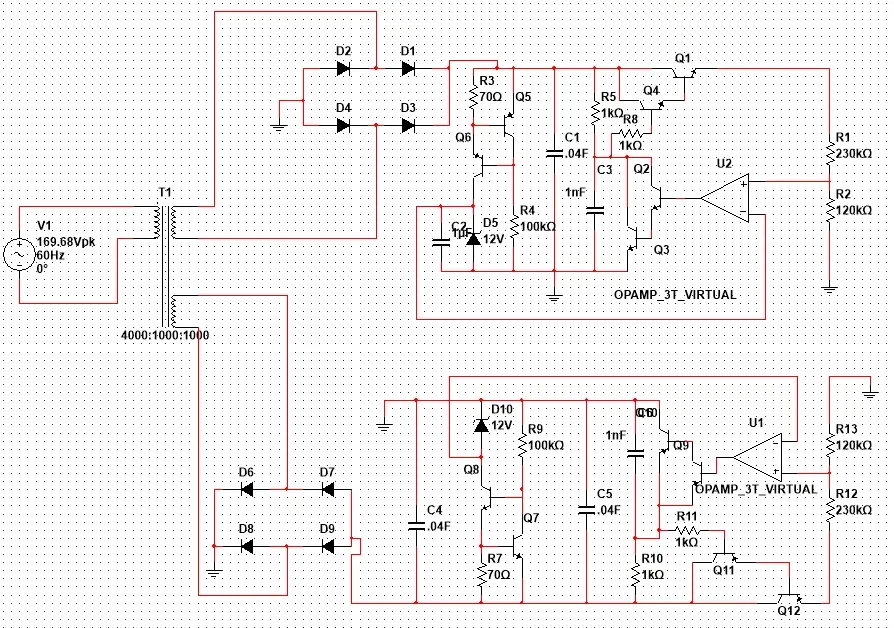
Figure 5: Power supply schematic
Here is an image of the first draft of the power supply schematic.
The schematic was created in Multisim Blue which is free to download from the Mouser website.
Using multisim we were able to simulate the power supply and observe the performance with differing loads. We began by using ideal components (transformer with no coil resistance, bridge rectifier with no voltage drop, etc) as a starting point.
To achieve the full 10A output we simulated 3.5 ohm loads attached to both 35V rails. Here is an image of the simulation:
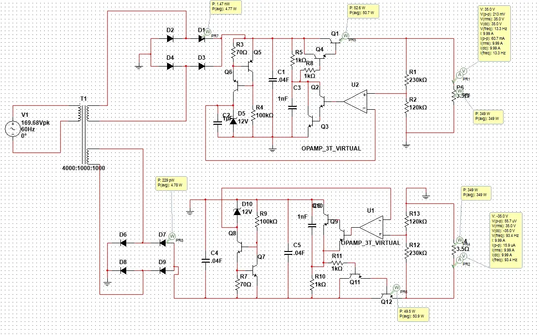
Figure 6: Power supply simulation
In the simulation we monitored the output voltage and current into our 3.5 ohm load along with the power consumption of the bridge rectifier and series pass transistors. These components generated the most heat in the circuit and will certainly need to be actively cooled.
At the full load of 3.5 ohms, the power loss due to the active components were:
Series pass transistor: 50.7 Watts
Bridge rectifier: 4.75 per diode = 19 Watts
Total Power loss per rail = 69.7 Watts
This figure shows the worst case scenario where both 35V rails are supplying the full 10A output. In reality the power supply will only be supplying power across one of the rails into the load.
Since the SSPS was designed to have two channels we needed two of these supplies. This would double our power handling needs from ~70 watts to ~140 watts.
Our water cooling solution should easily be able to handle our thermal load of ~140 watts.
Next Steps
In the next SSPS Design post we dig deeper into our component’s non-ideal characteristics and how that impacts our results. We will also look at the packaging and how we plan to lay out the transformers, cooling system, opamps, and control circuitry.
Related Topics
Super Simple Power Supply “SSPS” Design (Part 3)
We've created the first functioning prototype of the super simple power supply and will see some initial performance tests.
Super Simple Power Supply “SSPS” Design (Part 1)
After adding feature after feature that we would like to see in a power supply, the initial design ended up being anything from simple.
About MacroFab
MacroFab offers comprehensive manufacturing solutions, from your smallest prototyping orders to your largest production needs. Our factory network locations are strategically located across North America, ensuring that we have the flexibility to provide capacity when and where you need it most.
Experience the future of EMS manufacturing with our state-of-the-art technology platform and cutting-edge digital supply chain solutions. At MacroFab, we ensure that your electronics are produced faster, more efficiently, and with fewer logistic problems than ever before.
Take advantage of AI-enabled sourcing opportunities and employ expert teams who are connected through a user-friendly technology platform. Discover how streamlined electronics manufacturing can benefit your business by contacting us today.